HOT WATER SANITIZING UNDERCOUNTER DISHMACHINES SERVICE MANUAL FOR JACKSON MODELS: JPX-140 JPX-160 JPX-200 An April 30, 2004 P/N 7610-002-68-17 (Revision E) Company Jackson MSC, Inc. P.O. BOX 1060 HWY. 25E BARBOURVILLE, KY. 40906 FAX (606) 523-9196 PHONE (606) 523-9795 www.jacksonmsc.
This page intentionally left blank.
TABLE OF CONTENTS SECTION I. DESCRIPTION PAGE INSTRUCTIONS Installation Instructions Chemical Dispensing Equipment Chemical Timer Adjustments Operation Instructions PC Board 1 2 3 5 7 II. TROUBLESHOOTING 8 III.
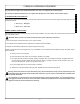
INSTALLATION INSTRUCTIONS I N S T R U C T I O N S VISUAL INSPECTION: Before installing the unit, check the container and machine for damage. A damaged container is an indicator that there may be some damage to the machine. If there is damage to both the container and machine, do not throw away the container. The dishmachine has been inspected and packed at the factory and is expected to arrive to you in new, undamaged condition.
CHEMICAL DISPENSING EQUIPMENT This page does not apply to the JPX-140 dishmachine. This unit is not supplied with chemical pumps. The JPX-160 and JPX-200 dishmachines are supplied with detergent and rinse additive chemical feeder pumps. I N TO PREPARE PUMPS FOR OPERATION S Locate the open ends of the chemical tubes, insert the end of each tube onto the hub on the brass weight, and place each one in the T R appropriate container. U A. Red Tubing = Detergent C T B.
CHEMICAL TIMER ADJUSTMENTS This page does not apply to the JPX-140 dishmachine. I N S T R U C T I O N S In general, it should not be necessary to alter the machine settings. The factory settings have been established to give the best results. IMPORTANT: To avoid wasting chemicals, remove tubes from soap and rinse-agent bottles before using the Service Mode. The system will always give an initial dose during the first cycle after switch-on, even though the wash tank may still be full.
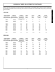
CHEMICAL TIMER ADJUSTMENTS CONTINUED Use the chart below to determine the initial time values for INITIAL RINSE, CYCLE RINSE, INITIAL SOAP, and CYCLE SOAP based on the desired concentration of the chemical being used. Check the concentration of the chemicals after running a few cycles and readjust as necessary. I JPX-160 Chemical Ratio Chemical (parts water to Concentration one part chemical) (percent in water) 5000 3000 2500 2000 1500 1000 800 600 400 300 250 200 0.02% 0.03% 0.04% 0.05% 0.07% 0.10% 0.
OPERATION INSTRUCTIONS I N S T R U C T I O N S PREPARATION: Before proceeding with the start-up of the unit, verify the following: that could be harmful to human beings. In order to do this, ware must be properly prepared prior to being placed in the machine. 1. Remove all solid wastes in order to avoid obstructing strainers, drain and wash jets. DAILY MACHINE PREPARATION: Refer to the section entitled “PREPARATION” at the top of this page and follow the instructions there.
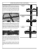
OPERATION INSTRUCTIONS (CONTINUED) JPX-140 Wash/Rinse Arm Assembly SHUTDOWN AND CLEANING: Remove the central knob (A) to remove the wash arms. Check the nozzles to ensure they are not clogged with debris. If they are, simply unscrew the nozzle retainer for the affected nozzle and remove it to clean out the debris. Flush the arms out with fresh water. IMPORTANT: Remove only one nozzle at a time to ensure that you replace all of the nozzles as required.
PC BOARD Display Contrast Adjuster. Turn clockwise to adjust the brightness of the display. It will not unscrew. When it reaches the brightest spot, it will restart at the dimmest setting. Red lights will illuminate when the corresponding output signal is “on”.
TROUBLESHOOTING SECTION WARNING: Inspection, testing and repair of electrical equipment should be performed only by qualified service personnel. Certain procedures in this section require electrical tests or measurements while power is applied to the machine. Exercise extreme caution at all times. If test points are not easily accessible, disconnect power, attach test equipment and reapply power to test. When replacing electrical parts, disconnect power at source circuit breaker.
SPECIFICATIONS of the JPX-140 PERFORMANCE/CAPABILITIES ELECTRICAL REQUIREMENTS OPERATING CAPACITY (RACKS/HOUR) WASH PUMP MOTOR HP RACKS PER HOUR 13 DISHES PER HOUR 91 GLASSES PER HOUR 260 J OPERATING CYCLE (SECONDS) P WASH TIME X RINSE TIME 1 TOTAL CYCLE TIME 4 0 NOTE: Typical Electrical Circuit is based upon (1) 125% of the full amperage load of the machine and (2) typical fixed-trip circuit breaker sizes as listed in the NEC 2002 Edition.
DIMENSIONS of the JPX-140 A. 1/2” FNPT 140BF. WATER CONNECTION 2 1/2” MIN. WALL CLEARANCE B. DRAIN HOSE CONNECTION FOR GRAVITY DRAIN FROM THE UNIT. UNIT SUPPLIED WITH 1” I.D. X 1 1/2” O.D. X 6’-0” LONG FLEXIBLE HOSE. C. ELECTRICAL CONNECTION J P X D.
FRONT ASSEMBLY 02 03 04 05 06 01 08 J P X 09 1 4 0 10 07 1 12 11 ITEM QTY DESCRIPTION Mfg. No.
ELECTRICAL PANEL 01 02 03 12 13 04 14 05 06 15 07 08 11 10 09 ITEM QTY DESCRIPTION Mfg. No.
FRONT AND BOTTOM VIEW 01 02 03 05 06 04 07 08 09 10 J P X 1 4 0 11 12 13 14 15 11 01 17 16 07 09 18 19 10 20 21 22 23 19 24 09 24 28 25 24 27 06 26 13
FRONT AND BOTTOM VIEW (CONTINUED) ITEM QTY DESCRIPTION Mfg. No.
WASH ARM/RINSE ARM ASSEMBLIES J P X 1 4 0 01 02 03 04 05 07 27 08 09 28 21 10 11 12 29 30 31 22 14 15 16 26 25 24 14 23 15 17 18 13 19 06 20
WASH ARM/RINSE ARM ASSEMBLIES (CONTINUED) ITEM QTY DESCRIPTION Mfg. No.
INSIDE TUB VIEW 02 03 04 07 08 01 05 09 J P X *14 11 1 4 0 12 *13 14 10 *06 * Represents an item not shown . ITEM QTY DESCRIPTION Mfg. No.
REAR VIEW 01 08 09 02 10 05 J P X 03 1 4 0 04 06 07 01 ITEM QTY DESCRIPTION Mfg. No.
MISCELLANEOUS 02 06 01 05 03 04 J P X 1 4 0 07 09 09 08 ITEM QTY DESCRIPTION Mfg. No.
JPX-140 ELECTRICAL DIAGRAM 208-240 VOLT, 60 HERTZ, 1 PHASE J P X 1 4 0 20
SPECIFICATIONS of the JPX-160 ELECTRICAL REQUIREMENTS PERFORMANCE/CAPABILITIES WASH PUMP MOTOR HORSEPOWER OPERATING CAPACITY (RACKS/HOUR) RACKS PER HOUR 24 DISHES PER HOUR 192 GLASSES PER HOUR 600 NOTE: Typical Electrical Circuit is based upon (1) 125% of the full amperage load of the machine and (2) typical fixed-trip circuit breaker sizes as listed in the NEC 2002 Edition. Local codes may require more stringent protection than what is displayed here.
DIMENSIONS of the JPX-160 2 1/2” MIN. WALL CLEARANCE A. 1/2” FNPT 140BF. WATER CONNECTION B. DRAIN HOSE CONNECTION FOR PUMPED DRAIN FROM THE UNIT. DISCHARGE HEIGHT MUST BE MAINTAINED. UNIT SUPPLIED WITH 1” I.D. X 1 1/2” O.D. X 6’-0” LONG FLEXIBLE HOSE. C.
JPX-160 FRONT VIEW 02 03 04 05 06 01 07 01 J P X 11 1 6 0 01 10 08 09 ITEM QTY DESCRIPTION Mfg. No.
ELECTRICAL PANEL 07 08 09 01 02 10 11 12 03 13 04 14 05 06 ITEM QTY DESCRIPTION Mfg. No.
FRONT AND BOTTOM VIEW 01 02 03 04 06 07 05 09 08 10 J P X 1 6 0 11 12 13 14 11 15 16 01 21 06 20 17 23 23 24 25 08 10 10 26 05 10 18 28 19 30 29 25 27 22
FRONT AND BOTTOM VIEW (CONTINUED) ITEM QTY DESCRIPTION Mfg. No.
REAR VIEW 01 05 J P X 03 1 6 0 02 04 ITEM QTY DESCRIPTION Mfg. No.
WASH ARM/RINSE ARM ASSEMBLIES 01 02 03 04 05 07 08 10 09 J P X 1 6 0 14 *18 19 20 21 *11 *12 *13 28 22 23 24 17 16 15 06
WASH ARM/RINSE ARM ASSEMBLIES (CONTINUED) J P X 1 6 0 ITEM QTY DESCRIPTION Mfg. No.
INSIDE TUB VIEW 01 02 03 04 05 06 07 08 09 *10 12 11 J P X 1 6 0 13 14 *15 *10 16 17 *18 ITEM QTY DESCRIPTION Mfg. No.
MISCELLANEOUS 07 08 01 02 03 J P X 04 05 *06 11 1 6 0 10 11 12 10 11 09 Front View Bottom Right Side View ITEM QTY DESCRIPTION Mfg. No.
JPX-160 ELECTRICAL DIAGRAM 208-240 VOLT, 60 HERTZ, 1 PHASE J P X 1 6 0 32
JPX-160 ELECTRICAL DIAGRAM 12 VOLT CIRCUIT J P X 1 6 0 33
JPX-160 COMPONENTS DIAGRAM J P X 1 6 0 34
SPECIFICATIONS of the JPX-200 ELECTRICAL REQUIREMENTS PERFORMANCE/CAPABILITIES WASH PUMP MOTOR HORSEPOWER OPERATING CAPACITY (RACKS/HOUR) RACKS PER HOUR 24 DISHES PER HOUR 600 GLASSES PER HOUR 600 NOTE: Typical Electrical Circuit is based upon (1) 125% of the full amperage load of the machine and (2) typical fixed-trip circuit breaker sizes as listed in the NEC 2002 Edition. Local codes may require more stringent protection than what is displayed here.
DIMENSIONS of the JPX-200 A. 1/2” FNPT 140BF. WATER CONNECTION 2 1/2” MIN. WALL CLEARANCE B. DRAIN HOSE CONNECTION FOR PUMPED DRAIN FROM THE UNIT. DISCHARGE HEIGHT MUST BE MAINTAINED. UNIT SUPPLIED WITH 1” I.D. X 1 1/2” O.D. X 6’-0” LONG FLEXIBLE HOSE. C.
MAIN ASSEMBLY 01 02 03 04 05 06 07 08 10 J P X 2 0 0 09 12 11 ITEM QTY DESCRIPTION Mfg. No.
ELECTRICAL PANEL 10 01 02 11 12 03 04 13 05 14 J P X 06 15 08 07 09 TEM QTY DESCRIPTION Mfg. No.
FRONT AND BOTTOM VIEW 01 02 03 04 06 05 07 08 J P X 2 0 0 09 10 11 12 17 13 08 18 14 04 15 20 16 20 21 22 07 05 23 08 24 19 25 26 05 28 25 39 08 29 25 27
FRONT AND BOTTOM VIEW (CONTINUED) ITEM QTY DESCRIPTION Mfg. No.
REAR VIEW 06 02 07 03 08 09 J P X 2 0 0 04 01 05 TEM QTY DESCRIPTION Mfg. No.
WASH ARM/RINSE ARM ASSEMBLIES 01 02 03 04 05 06 08 07 J P X 2 0 0 09 10 11 12 13 14 15 16 17 18 19 20 ITEM QTY DESCRIPTION Mfg. No.
INSIDE TUB VIEW 01 02 03 06 04 05 07 08 *09 10 11 12 13 J P X 14 2 0 0 *13 12 05 12 04 * Indicates Item Not Shown ITEM QTY DESCRIPTION Mfg. No.
MISCELLANEOUS 01 07 02 03 04 05 *06 J P X 08 11 2 0 0 09 10 12 ITEM QTY DESCRIPTION Mfg. No.
JPX-200 ELECTRICAL DIAGRAM 208-230 VOLT, 60 HERTZ, 1 PHASE J P X 2 0 0 45
JPX-200 ELECTRICAL DIAGRAM 12 VOLT CIRCUIT J P X 2 0 0 46
JPX-200 COMPONENTS DIAGRAM J P X 2 0 0 47