DUAL TEMPERATURE, GAS HEATED, DOOR-TYPE DISHMACHINES TECHNICAL MANUAL INSTALLATION MANUAL FOR EXPORT UNITS SERVICE MANUAL FOR DOMESTIC UNITS FOR JACKSON MODELS: TEMPSTAR GPX TEMPSTAR HH GPX August 6, 2007 P/N 7610-002-57-32 (Revision D) Jackson MSC, INC. P.O. BOX 1060 HWY. 25E BARBOURVILLE, KY. 40906 FAX (606) 523-9196 PHONE (606) 523-9795 www.jacksonmsc.
REVISION/ PAGE REVISION DATE MADE APPLICABLE BY ECN C 06-08-04 MAW 7006 Changed thermostat bracket from 17372 to 18164. Changed to new layout. D 07-24-06 MAW 7445, 7553 7571 Converted to centered layout. Replace 05700-002-63-16 with 04730-207-15-00 nipple. Add false panel assembly and wash thermostat kits. 3 08-06-07 MAW PROCESS Corrected 110V amps from 14 to 24.
NOMENCLATURE FOR THE MODELS COVERED IN THIS MANUAL TEMPSTAR HH GPX TEMPSTAR GPX = Gas heated, hot water sanitizing, door-type dishmachine TEMPSTAR HH GPX = Gas heated, hot water sanitizing, door-type dishmachine with higher hood Model: Serial No.: Installation Date: Service Rep. Name: Phone No.
TABLE OF CONTENTS Section I. Description Page SPECIFICATION INFORMATION Specifications of the Tempstar GPX Specifications of the Tempstar HH GPX Dimensions for the Tempstar GPX Dimensions for the Tempstar HH GPX Table Dimensions 2 3 4 5 6 INSTALLATION/OPERATION INSTRUCTIONS Installation Instructions Electrical Installation Instructions Gas Booster Heater Connection Operation Instructions 8 9 10 12 III. PREVENTATIVE MAINTENANCE 15 IV. TROUBLESHOOTING 17 V.
SECTION 1: SPECIFICATION INFORMATION 1
SECTION 1: SPECIFICATION INFORMATION SPECIFICATIONS OF THE TEMPSTAR GPX PERFORMANCE/CAPABILITIES ELECTRICAL REQUIREMENTS OPERATING CAPACITY (RACKS/HOUR) RACKS PER HOUR 57 DISHES PER HOUR 1425 GLASSES PER HOUR 1425 45 RINSE TIME 11 DWELL TIME 2 TOTAL CYCLE TIME 60 1/8 110 - 120 208 - 240 8.
SECTION 1: SPECIFICATION INFORMATION SPECIFICATIONS OF THE TEMPSTAR HH GPX PERFORMANCE/CAPABILITIES ELECTRICAL REQUIREMENTS OPERATING CAPACITY (RACKS/HOUR) RACKS PER HOUR 53 DISHES PER HOUR 1325 GLASSES PER HOUR 1325 SELECTION (A) 45 RINSE TIME 15 TOTAL CYCLE TIME 60 2.0 RECIRCULATOR PUMP MOTOR HP 1/8 NOTE: Typical Electrical Circuit is based upon (1) 125% of the full amperage load of the machine and (2) typical fixed-trip circuit breaker sizes as listed in the NEC 2002 Edition.
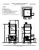
SECTION 1: SPECIFICATION INFORMATION DIMENSIONS FOR TEMPSTAR GPX A - DRAIN 1 1/2” NPT B - WATER INLET 1/2” NPT C - ELECTRICAL CONNECTION D - STANDARD WALL CLEARANCE WITH DISHTABLE 4” E - OUTLET TO BOOSTER HEATER 3/4” NPT F - INLET FROM BOOSTER HEATER 3/4” NPT LEGEND D D 4 7/8” C 25 1/4” 32” D C ALL DIMENSIONS ARE +/- 1/2” DUE TO ADJUSTABLE FEET.
SECTION 1: SPECIFICATION INFORMATION DIMENSIONS FOR TEMPSTAR HH GPX LEGEND: D A - DRAIN 1 1/2” NPT B - WATER INLET 1/2” NPT C - ELECTRICAL CONNECTION D - STANDARD WALL CLEARANCE WITH DISHTABLE 4” E - OUTLET TO BOOSTER HEATER 3/4” N.P.T. F - INLET FROM BOOSTER HEATER 3/4” N.P.T. ALL DIMENSIONS ARE +/- 1/2” DUE TO ADJUSTABLE FEET.
SECTION 1: SPECIFICATION INFORMATION 4” MINIMUM 25 1/4” 20 1/2” OPENING 2 1/2” TABLE DIMENSIONS TABLE DIMENSIONS CORNER INSTALLATION 2 1/2” 20 1/2” OPENING 4” MINIMUM 25 1/4” 3/4” 1 1/2” ROLL TABLE DIMENSIONS CONNECTION TO DISHMACHINE 20 1/2” OPENING 25 1/4” 4” MINIMUM 2 1/2” 20 1/2” TABLE DIMENSIONS STRAIGHT THROUGH INSTALLATION 25 1/4” Tempstar/HH GPX Series Technical Manual 7610-002-57-32 Issued: 07-24-2006 Revised: N/A 6
SECTION 2: INSTALLATION/OPERATION INSTRUCTIONS 7
SECTION 2: INSTALLATION/OPERATION INSTRUCTIONS INSTALLATION INSTRUCTIONS VISUAL INSPECTION: Before installing the unit, check the container and machine for damage. A damaged container is an indicator that there may be some damage to the machine. If there is damage to both the container and machine, do not throw away the container. The dishmachine has been inspected and packed at the factory and is expected to arrive to you in new, undamaged condition.
SECTION 2: INSTALLATION/OPERATION INSTRUCTIONS INSTALLATION INSTRUCTIONS GAS BOOSTER HEATER ELECTRICAL INSTALLATION: The gas booster heater must have a separate electric hookup than that supplied to the dishmachine. Please refer to the manual supplied with your gas booster heater. GAS CONNECTION TO THE BOOSTER HEATER: Please refer to the manual supplied with your gas booster heater. VENTILATION OF THE GAS BOOSTER HEATER: Please refer to the manual supplied with your gas booster heater.
SECTION 2: INSTALLATION/OPERATION INSTRUCTIONS GAS BOOSTER HEATER CONNECTIONS WARNING ENSURE THAT THERE IS NO ELECTRICAL POWER APPLIED TO THE MACHINE WHEN MAKING GAS CONNECTION. CHECK ALL GAS CONNECTIONS FOR LEAKS PRIOR TO APPLYING POWER. THE GASES USED FOR COMBUSTION IN THIS DISH MACHINE ARE HIGHLY FLAMMABLE. DO NOT SMOKE AROUND THIS MACHINE. ENSURE THAT THE AREA WHERE THIS MACHINE IS TO BE INSTALLED IS WELL-VENTILATED TO PREVENT THE BUILD-UP OF COMBUSTIBLE GASES.
SECTION 2: INSTALLATION/OPERATION INSTRUCTIONS GAS BOOSTER HEATER CONNECTIONS (CONTINUED) VACUUM BREAKER RINSE ARM PRESSURE GAGE DISHMACHINE PRESSURE REGULATING VALVE BUILDINGS WATER SUPPLY * HEATING COIL PHOSPHATE WATER TREATMENT CARTRIDGE Y-STRAINER 3/4" HOSE RINSE SOLENOID VALVE RECIRC PUMP AN ASTERISK ( ) DENOTES ITEMS INCLUDED WITH THE GAS BOOSTER HEATER * BOOSTER * GASHEATER S * PRESSURE RELIEF VALVE 3/4" HOSE INLET * OUTLET DRAIN VALVE TEMPERATURE/PRESSURE GAGE * TEMPERATURE/PR
SECTION 2: INSTALLATION/OPERATION INSTRUCTIONS OPERATION INSTRUCTIONS PREPARATION: Before proceeding with the start-up of the unit, verify the following: 1. The pan strainer and pump suction strainer are in place and are clean. 2. The overflow tube and o-ring are installed. 3. That the wash and rinse arms are screwed securely into place and that their endcaps are tight. The wash and rinse arms should rotate freely.
SECTION 2: INSTALLATION/OPERATION INSTRUCTIONS OPERATION INSTRUCTIONS (CONTINUED) OPERATIONAL INSPECTION: Based upon usage, the pan strainer may become clogged with soil and debris as the workday progresses. Operators should regularly inspect the pan strainer to ensure it has not become clogged. If the strainer does, it will reduce the washing capability of the machine. Instruct operators to clean out the pan strainer at regular intervals or as required by work load.
SECTION 3: PREVENTATIVE MAINTENANCE 14
SECTION 3: PREVENTATIVE MAINTENANCE PREVENTATIVE MAINTENANCE The dishmachines covered in this manual are designed to operate with a minimum of interaction with the operator. However, this does not mean that some items will not wear out in time. Jackson highly recommends that any maintenance and repairs not specifically discussed in this manual should be performed by QUALIFIED SERVICE PERSONNEL ONLY.
SECTION 4: TROUBLESHOOTING 16
SECTION 4: TROUBLESHOOTING COMMON PROBLEMS WARNING: Inspection, testing and repair of electrical equipment should be performed only by qualified service personnel. Certain procedures in this section require electrical tests or measurements while power is applied to the machine. Exercise extreme caution at all times. If test points are not easily accessible, disconnect power, attach test equipment and reapply power to test. When replacing electrical parts, disconnect power at source circuit breaker.
SECTION 4: TROUBLESHOOTING COMMON PROBLEMS (CONTINUED) Problem: Rinse water not reaching required temperature. 1. Faulty rinse heater. Check element for continuity; if open, replace heater. 2. Misadjusted/faulty thermostat(s). Verify operation and setting of thermostats, replace if necessary. 3. Rinse thermometer is defective. Replace thermometer. Problem: Wash water is not reaching required temperature. 1. Faulty wash heater. Check element for continuity; if open, relace the heater. 2.
SECTION 5: SERVICE PROCEDURES 19
SECTION 5: SERVICE PROCEDURES RINSE SOLENOID VALVE REPAIR PARTS KIT These dishmachines are equipped with electrical solenoid valves to allow for automatic fill and rinse. These valves are designed to specific tolerances and design aspects that must be met in order to function properly.
SECTION 5: SERVICE PROCEDURES RINSE SOLENOID VALVE REPAIR PARTS KIT (CONTINUED) Loosening the conduit nut Prying open the coil wire cover 7. Using a pair of channel locks, gently loosen the conduit retaining ring for the conduit nut. Once it is loosened, use your fingers to unscrew and remove it. 4. When replacing the coil, ensure that when removing the coil wire cover that care is taken not to damage the wires inside.
SECTION 5: SERVICE PROCEDURES RINSE SOLENOID VALVE REPAIR PARTS KIT (CONTINUED) Removing the valve bonnet Removing the diaphragm 13. Slowly remove the valve bonnet. Note: The spring for the plunger is located directly under the bonnet and may come free if you are not careful. Remove the plunger, spring and valve bonnet and place to the side. 17. Remove the diaphragm retainer and then the diaphragm itself.
SECTION 5: SERVICE PROCEDURES RINSE SOLENOID VALVE REPAIR PARTS KIT (CONTINUED) 21. With the mesh screen removed, look down into the valve and verify it is not clogged. Remove any foreign objects from the valve body that would obstruct flow. 22. Reassemble the valve, reversing the steps needed to take it apart. Replace defective replacement parts with new parts from ordered kits. Ensure that components are sufficiently tightened to prevent leakage.
SECTION 5: SERVICE PROCEDURES VACUUM BREAKER REPAIR PARTS KIT These dishmachines are equipped with vacuum breakers to serve as back-flow prevention devices. ASSE requirements specify what type of back-flow prevention is necessary on dishmachines. Vacuum breakers, unlike air gaps, have certain parts that have specific tolerances and design aspects that must be met in order to function properly.
SECTION 5: SERVICE PROCEDURES VACUUM BREAKER REPAIR PARTS KIT (CONTINUED) 7. If any of these conditions are present, replace the old plunger with the new one from your kit. Verify that the new plunger is also free from defects. If it is not, contact your Ecolab representative immediately. 8. The plunger should drop into the vacuum breaker and seat. Ensure it is not flipped upside down (the orange seal ring should be up towards the top of the vacuum breaker). 9. Pick up the cap and examine it.
SECTION 6: PARTS SECTION 26
SECTION 6: PARTS SECTION TEMPSTAR GPX CONTROL BOX ASSEMBLY 5 6, 4, 3 20, 17 7 1 8, 9 10, 4 11, 4 2, 4 11, 4 23, 24 25, 4 13, 12 16 22 21 19, 4 15 Tempstar/HH GPX Series Technical Manual 7610-002-57-32 Issued: 07-24-2006 Revised: N/A 27 14 18
SECTION 6: PARTS SECTION TEMPSTAR GPX CONTROL BOX ASSEMBLY (CONTINUED) ITEM QTY 1 2 3 4 5 6 7 8 9 10 11 12 13 14 15 16 17 18 19 20 21 22 23 24 25 26* 27* 28* 29* 30* 31* 32* 1 1 1 6 4 1 1 1 2 1 2 8 2 1 1 1 1 1 1 1 1 1 1 4 1 1 1 1 4 4 4 4 DESCRIPTION Mfg. No.
SECTION 6: PARTS SECTION Tempstar/HH GPX Series Technical Manual 7610-002-57-32 Issued: 07-24-2006 Revised: N/A 29 1, 2, 3 4 5, 6 7, 8 9 17, 18 19, 20 5, 6 21, 22, 20 10 11 23, 13 16 24, 25 14, 15 12, 13 26*, 27* 28 29 30 TEMPSTAR HH GPX CONTROL BOX ASSEMBLY
SECTION 6: PARTS SECTION TEMPSTAR HH GPX CONTROL BOX ASSEMBLY (CONTINUED) ITEM QTY DESCRIPTION Mfg. No. 1 2 3 4 5 6 7 8 * 9 10 11 12 13 14 15 16 17 18 19 20 21 22 22 23 24 25 26* 27* 28 29 30 * 1 9 9 1 2 4 1 3 1 1 1 1 1 8 2 3 1 1 1 1 4 1 1 1 1 1 4 1 1 1 1 1 1 Bracket, Electrical Box Mounting Locknut, 1/4"-20 S/S Hex with Nylon Insert Washer, 1/4"-20 I.D.
SECTION 6: PARTS SECTION TEMPSTAR GPX HOOD ASSEMBLY 1 2, 3 4* 7 6 5 Magnetic Reed Switch 05930-011-47-50 Switch Box Weldment 05700-002-14-34 ITEM QTY DESCRIPTION Mfg. No. 1 2 3 4* 5 6 7 1 2 6 1 8 8 14 Hood, Single Piece Weldment Bracket, Cantilever Support Wear Button .50 Dia. Conduit Bracket (not shown) Bolt, 1/4”-20 x 1/2” S/S Hex Head Washer, 1/4” I.D.
SECTION 6: PARTS SECTION TEMPSTAR HH GPX HOOD ASSEMBLY * Represents an item not shown. 4 1 2 3 3 4 2 5 5 11 *9 12 6 *10 7 8 6 *7 *8 ITEM QTY DESCRIPTION Mfg. No.
SECTION 6: PARTS SECTION FRAME ASSEMBLIES Front Panel Tempstar GPX 05700-002-36-65 Bolt, 1/4”-20 x 1/2” 05305-274-02-00 Locknut, 1/4”-20 S/S ] Hex with Nylon Insert 05310-374-02-00 Frame Weldment Tempstar GPX 05700-031-48-01 Bullet Foot 05340-108-01-03 Panel, Front Tempstar HH GPX 05700-002-01-42 Frame Weldment Tempstar HH GPX 05700-002-03-49 Bullet Foot 05340-108-02-06 Tempstar/HH GPX Series Technical Manual 7610-002-57-32 Issued: 07-24-2006 Revised: N/A 33
SECTION 6: PARTS SECTION TUB ASSEMBLY 2 3 4 5 6 7 8 11 9, 10 12 13, 10 14 31 30 1 3 15 16 28, 29 15 17 18, 10 19 SEE PAGE ENTITLED “WASH MOTORS” 20 21, 22 23 24 25, 26 * Represents an item not shown.
SECTION 6: PARTS SECTION TUB ASSEMBLY (CONTINUED) ITEM QTY DESCRIPTION Mfg. No.
SECTION 6: PARTS SECTION CANTILEVER ARM/DOOR ASSEMBLIES TEMPSTAR GPX 2 10, 11, 12 24, 18 3 1 13 4 14 5 23, 18 6 9 15, 16 7 8 17, 18 21, 25 20 19, 11, 12 22 Washer, Nylon 05311-369-03-00 Bushing 03120-100-03-00 Cotter Pin 3/32" x 3/4" 05315-207-01-00 Clevis Pin 05315-700-01-00 Yoke 05700-000-75-78 Nut, 3/8"-16 S/S Hex Locking 05310-256-04-00 Tempstar/HH GPX Series Technical Manual 7610-002-57-32 Issued: 07-24-2006 Revised: N/A 36
SECTION 6: PARTS SECTION CANTILEVER ARM/DOOR ASSEMBLIES TEMPSTAR GPX (CONTINUED) ITEM QTY DESCRIPTION Mfg. No.
SECTION 6: PARTS SECTION CANTILEVER ARM/DOOR ASSEMBLIES TEMPSTAR HH GPX 1 2 10 9 3, 4, 5 8 6 7 11 17, 18 17, 18 35, 24 12 36, 22 33, 34 29, 30 13 31, 32 19, 20 12 14 15 21, 22 23, 4, 24 25, 4, 5 26 28 27, 22 Tempstar/HH GPX Series Technical Manual 7610-002-57-32 Issued: 07-24-2006 Revised: N/A 38 16
SECTION 6: PARTS SECTION CANTILEVER ARM/DOOR ASSEMBLIES TEMPSTAR HH GPX (CONTINUED) ITEM QTY DESCRIPTION Mfg. No.
SECTION 6: PARTS SECTION INLET PLUMBING ASSEMBLIES TEMPSTAR GPX 1 1 CONNECTS TO THE WASH TANK HEATING COIL OUTLET 2 NOTE: ENSURE DIRECTION OF FLOW THROUGH THE PRESSURE REGULATING VALVE IS IN THE CURRECT DIRECTION. 1 3 7 4 5 6 ITEM QTY DESCRIPTION Mfg. No.
SECTION 6: PARTS SECTION RINSE HEADER PLUMBING ASSEMBLY Rinse Header Plumbing Assembly, Tempstar GPX Rinse Header Plumbing Assembly, Tempstar HH GPX 05700-002-56-67 05700-002-58-02 Vacuum Breaker, 1/2" 04820-003-06-13 Rinse Tube Assembly, Tempstar GPX 05700-002-56-68 Rinse Tube Assembly, Tempstar HH GPX 05700-002-58-03 Ball Valve, 1/4" 04810-011-72-67 Pressure Gauge, 0-100 PSI 06685-111-88-34 ITEM QTY DESCRIPTION * 1 1 1 Rinse Hose Assembly Hose, 1/2” x 27” Fitting, 1/2” Mfg. No.
SECTION 6: PARTS SECTION RECIRCULATING PLUMBING ASSEMBLY 4 1 5 2 * The hardware is included with pump flange (item 7). 11 3 4 * 6 10 9 8 7 7 * The gaskets are included with the pump (item 6). ITEM QTY DESCRIPTION Mfg. No.
SECTION 6: PARTS SECTION RINSE SOLENOID VALVE & VACUUM BREAKER REPAIR PARTS KITS Screw Data Plate Cap Screw Coil & Housing Data Plate Valve Bonnet Spring position is moved for clarity. Goes below the plunger.
SECTION 6: PARTS SECTION WASH & RINSE ARM/MANIFOLD ASSEMBLIES (TEMPSTAR GPX) 18 19 11 13 18 16 12 15 14 Rinse Injector Weldment 1 per machine 05700-002-56-75 18 Plug, 1/8” NPT, Brass 3 per Rinse Injector 04730-209-07-37 18 DETAIL “A” FINAL RINSE ARMS & MANIFOLD 2, 3, 4 Rinse Injector Gasket 2 per machine 05330-111-42-81 5 5 1 1 10 7 9 9, 10 6, 18 7 9 9, 10 17 16, 8 5 5 16 2, 3, 20 DETAIL “B” WASH ARMS & MANIFOLD Tempstar/HH GPX Series Technical Manual 7610-002-57-32 Issued: 07-24-2006 Re
SECTION 6: PARTS SECTION WASH & RINSE ARM/MANIFOLD ASSEMBLIES (TEMPSTAR GPX) (CONTINUED) ITEM QTY DESCRIPTION Mfg. No.
SECTION 6: PARTS SECTION WASH & RINSE ARM/MANIFOLD ASSEMBLIES (TEMPSTAR HH GPX) 18 19 13 11 16 18 14 12 15 18 Rinse Injector Weldment 1 per machine 05700-002-56-75 15 Plug, 1/8” NPT, Brass 3 per Rinse Injector 04730-209-07-37 18 DETAIL “A” FINAL RINSE ARMS & MANIFOLD 2, 3, 4 5 1 5 1 9, 10 10 7 9 6, 18 7 21 21 17, 8 5 17 DETAIL “B” WASH ARMS & MANIFOLD 5 2, 3, 20 Tempstar/HH GPX Series Technical Manual 7610-002-57-32 Issued: 07-24-2006 Revised: N/A 46
SECTION 6: PARTS SECTION WASH & RINSE ARM/MANIFOLD ASSEMBLIES (TEMPSTAR HH GPX) (CONTINUED) ITEM QTY DESCRIPTION Mfg. No.
SECTION 6: PARTS SECTION COIL ASSEMBLY Complete Coil Assembly 05700-002-08-62 Stand C, Coil Support 05700-002-08-52 Coil Weldment 05700-021-41-38 Stand D, Coil Support 05700-002-08-53 Stand B, Coil Support 05700-002-08-51 Stand A, Coil Support 05700-002-08-50 Gasket, Coil 4 per assembly 05700-001-17-86 Washer, Coil 2 per assembly 05700-001-17-87 Adapter, Coil Nut 2 per assembly 05700-011-17-85 Tempstar/HH GPX Series Technical Manual 7610-002-57-32 Issued: 07-24-2006 Revised: N/A 48
SECTION 6: PARTS SECTION EXHAUST FAN CONTROL OPTION/SAFETY DOOR INTERLOCK (SDI) OPTION Exhaust Fan Control Terminal Board 05940-011-84-41 Exhaust Fan Control 2” Din Rail 05700-002-36-09 Exhaust Fan Control Delay Timer 05945-011-65-44 Safety Door Interlock Box Bottom 05700-001-21-26 Safety Door Interlock Box Cover 05700-001-21-27 Other Safety Door Interlock (SDI) components (not shown): Pipe Clamp (found on the side of the machine) Solenoid, Electrical Interlock Option Relay 05700-000-35-05 04810-100-
SECTION 6: PARTS SECTION TEMPSTAR GPX FALSE PANEL INSTALLATION Left & Front False Panel Weldment 05700-002-75-52 Rack rail removed & repositioned for a corner operation. Right False Panel Weldment (Use with Overflow Tube Lifter) 05700-002-98-85 Left & Front False Panel Kit 05700-002-75-59 Right False Panel Kit (Use with Overflow Tube Lifter) 05700-002-98-86 False panel positioned in unit. 1. Loosen the rack assembly from the unit. 2. False panel will mount to the rack; inside the dishmachine. 3.
SECTION 6: PARTS SECTION TEMPSTAR HH GPX FALSE PANEL INSTALLATION False Panel 05700-002-52-54 Rack rail removed and repositioned for a corner operation. Kit, False Panel with Mounting Hardware 05700-002-52-89 False Panel Positioned in unit. 1. Remove the rack assembly from the dishmachine. 2. The false panel will mount inside of the dishmachine. 3. Position the panel in the dishmachine on the side to be closed. 4. Hold the panel against the side of the dishmachine and push upward. 5.
SECTION 6: PARTS SECTION DRAIN QUENCH ASSEMBLY Elbow, 1-1/2” 90B Street 04730-206-32-00 Drain Quench Assembly 06401-002-59-52 Nipple, 1-1/2” NPT 04730-207-40-00 Modified Compression Fitting 05700-001-16-52 Lid, Drain Quench 05700-002-67-16 Thermostat 05930-003-13-65 Solenoid Valve 04810-100-09-18 Reducer, 1-1/2” x 1/4” 04730-002-55-76 To Dishmachine Drain To Cold Water Supply Tee, 1-1/2” x 1-1/2” x 1-1/2” 04730-011-69-93 Reducer, 1-1/2” to 1/2” 04730-002-55-75 Box, Drain Quench 05700-002-69-96 Valv
SECTION 7: ELECTRICAL SCHEMATICS 53
SECTION 7: ELECTRICAL SCHEMATICS TEMPSTAR GPX 115 VOLT - 50/60 HERTZ - SINGLE PHASE Tempstar/HH GPX Series Technical Manual 7610-002-57-32 Issued: 07-24-2006 Revised: N/A 54
SECTION 7: ELECTRICAL SCHEMATICS TEMPSTAR GPX 208-230 VOLT - 50/60 HERTZ - SINGLE PHASE Tempstar/HH GPX Series Technical Manual 7610-002-57-32 Issued: 07-24-2006 Revised: N/A 55
SECTION 7: ELECTRICAL SCHEMATICS TEMPSTAR HH GPX 115 VOLT - 50/60 HERTZ - SINGLE PHASE Tempstar/HH GPX Series Technical Manual 7610-002-57-32 Issued: 07-24-2006 Revised: N/A 56
SECTION 7: ELECTRICAL SCHEMATICS TEMPSTAR HH GPX 208-230 VOLT - 50/60 HERTZ - SINGLE PHASE Tempstar/HH GPX Series Technical Manual 7610-002-57-32 Issued: 07-24-2006 Revised: N/A 57
SECTION 7: ELECTRICAL SCHEMATICS EXHAUST FAN CONTROL OPTION/SAFETY DOOR INTERLOCK (SDI) OPTION Tempstar/HH GPX Series Technical Manual 7610-002-57-32 Issued: 07-24-2006 Revised: N/A 58