
Installation Sheet

j a c l o i n d u s t r i e s | 129 Dermody Street Cranford, NJ 07016
p 908.653.4433 | 800.852.3906 f 908.653.1717 | 800.852.4133
REVISED 8.26.2016
JACLO.COM
|
PG 3
Critical support
area back wall
Critical support
area service wall
Critical support
area non-service
48”
24” (3 wall
stall)
Shower Bathing Area
Decorative ring
(not common to all
Flange
#10 Wood
screws
Escutcheon
O-ring
Installation Notes:
The #10 screws provided are for installation into wood, (proper installation requires all supplied screws be
used). The installer should provide hardware for other installation applications. Use flat head fasteners only.
When properly installed this product has been tested to meet or exceed loads mandated by the Americans
with Disabilities Act and ASTM F446, (minimum 250lbs / 113kg). (However, it is the responsibility of the
architect, builder and installer to ensure that the mounting area is secure and that proper
mounting hardware is used.)
Installation:
1. Position grab bar as required and mark hole pattern.
2. Remove grab bar and pre-drill hole pattern for #10 screws.
3. Install o-ring onto grab bar flange
4. Where applicable, install decorative ring onto end of flange.
5. Position grab bar, o-ring and decorative ring into place by aligning pre-drilled holes and flange hole pattern.
6. Attach to mounting surface using all #10 screws provided.
7. Slide escutcheon around bend and press into place over flange o-ring. Wetting o-ring aids with installation.
11/19/09
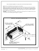
CRITICAL SUPPORT
AREA BACK WALL
CRITICAL SUPPORT
AREA SERVICE WALL
CRITICAL SUPPORT
AREA NON-SERVICE
SHOWER BATHING AREA
24” (60.96cm) (3 WALL STALL)
32”
(81.3cm) (2 WALL STALL)
48” (121.9cm)
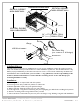
Flange
O-ring
#10 Wood screws
Escutcheon
Decorative Ring
(not common to all designs)
GNG-660
Critical support
area back wall
Critical support
area service wall
Critical support
area non-service
48”
24” (3 wall
stall)
Shower Bathing Area
Decorative ring
(not common to all
Flange
#10 Wood
screws
Escutcheon
O-ring
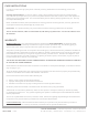
Installation Notes:
The #10 screws provided are for installation into wood, (proper installation requires all supplied screws be
used). The installer should provide hardware for other installation applications. Use flat head fasteners only.
When properly installed this product has been tested to meet or exceed loads mandated by the Americans
with Disabilities Act and ASTM F446, (minimum 250lbs / 113kg). (However, it is the responsibility of the
architect, builder and installer to ensure that the mounting area is secure and that proper
mounting hardware is used.)
Installation:
1. Position grab bar as required and mark hole pattern.
2. Remove grab bar and pre-drill hole pattern for #10 screws.
3. Install o-ring onto grab bar flange
4. Where applicable, install decorative ring onto end of flange.
5. Position grab bar, o-ring and decorative ring into place by aligning pre-drilled holes and flange hole pattern.
6. Attach to mounting surface using all #10 screws provided.
7. Slide escutcheon around bend and press into place over flange o-ring. Wetting o-ring aids with installation.
11/19/09
CRITICAL SUPPORT
AREA BACK WALL
CRITICAL SUPPORT
AREA SERVICE WALL
CRITICAL SUPPORT
AREA NON-SERVICE
SHOWER BATHING AREA
24”
(60.96cm) (3 WALL STALL)
32” (81.3cm) (2 WALL STALL)
48”
(121.9cm)
Flange
O-ring
#10 Wood screws
Escutcheon
Decorative Ring
(not common to all designs)
GNG-660
Where applicable, install o-ring onto grab bar ange.