
Installation & Assembly


06.9882 GOI
5
4.1
4.2
ENGLISH
~
ESPANOL
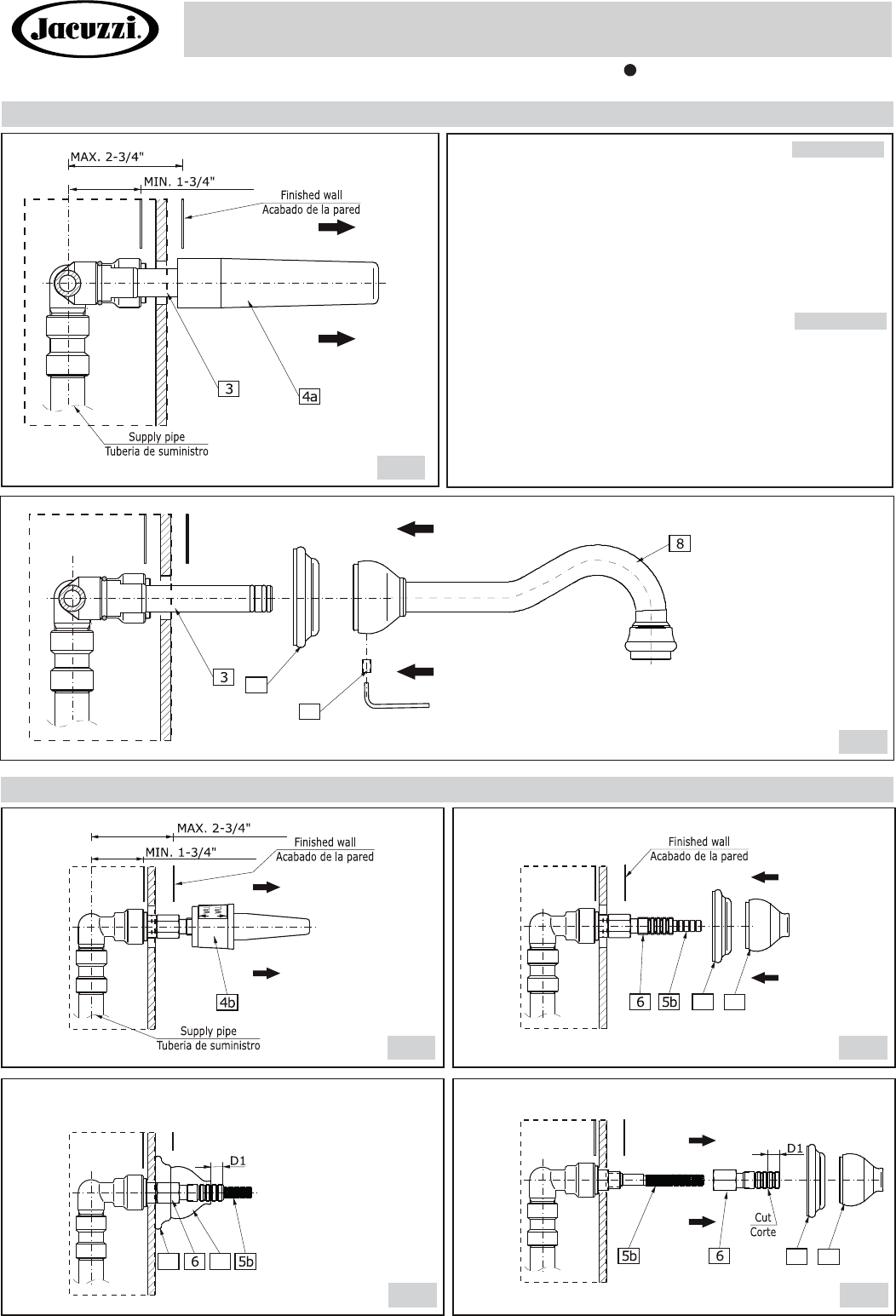
SPOUT INSTALATION • INSTALACIÓN DEL CAÑO
See fig 4.1-4.2
Remove cap protector (4a) by turning and pulling.
Insert spout base (9) over the tube of spout (3).
Slide spout (8) over tube of spout (3) until snug against finished
wall. Finished wall has to be between the MAX [3-3/4"] and MIN
[1-3/4"].
Attach spout (8) with hex socket screw (19). Use provided hex
key (K).
1.
2.
3.
4.
Vea dis. 4.1-4.2
Quite el tapón de protección (4a) girando y tirando.
Coloque la base del caño (9) en el tubo del caño (3).
Coloque el caño (8) sobre el tubo del caño (3) hasta que toque la
pared. La pared acabada tiene que ser entre MAX [3-3/4"] y
MIN [1-3/4"].
Una el caño (8) con el tornillo de zócalo con tuerca hexagonal
(19). Utilice la llave de tuerca hexagonal (K), proporcionada.
1.
2.
3.
4.
19
9
HANDLES INSTALLATION • INSTALACIÓN DE LAS MANILLAS
9 10
5.1 5.2
5.3 5.4
9 10
9 10
(70mm)
(44mm)
(70mm)
(44mm)
Rev. 3 December 2017
This product complies with NSF61/9, ASME/ANSI A112.18.1
and CSA B 125 Standards.
Installation Instructions Instrucciones de Instalación
BARREA™
WALL-MOUNTED LAVATORY FAUCET
GRIFO MONTADO EN LA PARED
BARREA™
BARREA™
Este producto cumple con los estándares requeridos por las normas
NSF61/9, ASME/ANSI A112.18.1 y CSA B 125.