
Operating Guide


Operating Manual
English
Page 6 www.jacuzzi.com
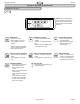
Pushbutton Whirlpool Schematic Diagram
CONTROL PANEL
PUMP/MOTOR
120VAC 20A
Dedicated GFCI
Circuit Required
CONTROL BOX
120 VAC
PUMP
FOR MODELS
WITH IN-LINE
HEATER
OR
PUMP
PUMP/MOTOR
120VAC 15A
Dedicated GFCI
Circuit Required
Whirlpool System Reference Illustrations
Fig. 6
J2 Control Panel Whirlpool Schematic Diagram
Fig. 7