
Installation Guide


ENGLISH
REMOTE LOCATION IN AN ADJACENT SPACE
RELOCATING THE BLOWER MOTOR
For convenience and/or accessibility, the blower motor and
fused control box can be installed in a remote location. The
blower motor and fused control box must be relocated as a
unit.
A separate circuit, which must be protected by a Ground
Fault Circuit Interrupter (GFCI), is required in the remote loca-
tion. Electrical connections should be performed by a licensed
electrician. The remote location must be service accessible.
The total length of the air pipe must not require more than
15' of piping and 6 directional changes. Pipe diameter must
be 1-1/2" or larger. Choose a space as close to the bath as
possible so the system works as efficiently as possible. This
space must be at least 30 cubic feet and the blower must be
mounted at least 2" above the floor and 2" minimum away
from any wall.
The blower must not be installed in an attic area.
NOTE: Do not remove the inverted U and check valve as
shown in the illustrations. Do not glue piping to the blower.
Blower is attached to the piping via a screw. Glue the air pipe
and let set overnight before attaching the blower with screw.
NOTE: Installing the Blower in a remote location will re-
duce system efficiency.
CAUTION: It is imperative to let the glued blower air pipe set
overnight as there may be fumes from the glue that could be
ignited if not allowed to dissipate.
Provide adequate ventilation in the remote location for
cooling the motor and to supply sufficient air for the blower.
The intake of the blower must not be blocked, restricted or
have any debris around it that can potentially be sucked
into blower.
Insulation on the air pipe length can reduce heat loss.
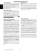
REMOTE LOCATION UNDER FLOOR
SCREW
CHECK VALVE
FLOW
CONTROL CABLE
TO BLOWER
CONNECT ONLY
TO A GFCI
PROTECTED
CIRCUIT
ADJACENT
SPACE
DO NOT REMOVE
INVERTED U
SCREW
CHECK
VALVE
FLOW
FLOOR
CONTROL
LINE
CONNECT ONLY TO A GFCI
PROTECTED CIRCUIT
DO NOT REMOVE
INVERTED U
Electrical Connections
DRAIN/OVERFLOW
For the air bath, a drain/overflow kit is included. This drain/
overflow kit must be used as it includes an electrically con-
trolled valve that allows the bath's air channels to drain when
the bath drain is opened. Refer to Drain Piping Assembly
Installation drawing.
Turn the bath upside down. Glue the 90° ell to the tee in
such a manner that it is sloping upward (with bath turned
upside down) to facilitate drainage making sure that any part
of the air channel drain piping assembly does not go above the
feet. Install drain overflow kit (provided). Connect the tubing
from the solenoid valve to the barbed fitting on the tail pipe and
secure with provided hose clamp.
Route the cables from solenoid valve and drain switch to
the control box and connect.
Note: When the bath is turned right side up it must be
propped up due to the length of the tail pipe.
SOLENOID
VALVE
TEE
TO CONTROL BOX
90° ELL
BARBED FITTING
TAIL PIPE
6
Jacuzzi Whirlpool Bath© BR28000A 3/05
DRAIN PIPING ASSEMBLY INSTALLATION
NOTE: Relocated blower requires a service access for the
control box and blower.