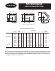
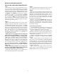
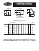
SHOWER BASE INSTALLATION INSTRUCTIONS E THRESHOLD SIDE THRESHOLD SIDE *A *A F A B B G C C C D D H B D RECTANGULAR SQUARE NEO-ANGLE * Add 1/8" for rough-in dimensions. PRODUCT CHART (TRU-LEVEL™) DIMENSIONS PRODUCT NO. MODEL NAME A B C D SQUARE S344000 S364000 S348000 3636S 4848S 4242S 36 48 42 36 48 42 17.5 23.25 20.25 18.0 24.0 21.
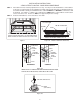
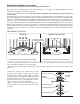
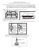
INSTALLATION INSTRUCTIONS 4 EASY STEPS TO INSTALL YOUR NEW SHOWER BASE STEP 1. STEP 2. If the subfloor is level, no other preparation is necessary. You can proceed to install the base. If the subfloor is not level, level shower base by spreading floor leveling compound, mortar, plaster or minimal expansion structural foam with a density of a minimum of 5 lbs./cubic ft. EVENLY over ENTIRE area where base will be installed. (See Figure 1.
STEP 3. Install cement board. CEMENT BOARD BLOCKING Figure 3 STEP 4. Install finishing materials and caulk base leaving 1/4" weep holes.
Detailed Installations Instructions Important: Read complete instructions before beginning installation. Each shower base is shipped with a shower drain and stainless steel strainer. An optional bright brass strainer isavailable for installation on the drain assembly. Remove the shower base from the carton. Do not destroy the shipping carton until after satisfactory inspection of the product. Immediately upon receipt, inspect the base before installing.
DETAILED INSTRUCTIONS FOR INSTALLING YOUR NEW SHOWER BASE STEP 3 Place cement board or equivalent on top of shower base flange and secure to studwall (see Figure 3). STEP 1 If the subfloor is level, no other preparation is necessary. You can proceed to install the base. If the subfloor is not level, level shower base by spreading floor leveling compound, mortar, plaster or minimal expansion structural foam having a density of a minimum of 5 lbs./cubic ft.
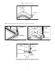
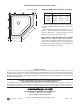
Determining Glass Enclosure Dimensions CL OF THRESHOLD ROUGH-IN DIMENSION CHART (Neo-Angle Only) C* MODEL A A B C* 3838N 16 3/4" 28" 1-3/8" 4242N 20-3/4" 27-3/8" 1-3/8" 4848N 26-3/4" 27-1/2" 1-3/8" *C represents the dimension from the stud wall to the face of the finishing materials used in the shower construction. If Jacuzzi Whirlpool Bath surround walls are used, subtract 1-3/8" from dimension A to arrive at glass enclosure dimensions.
Jacuzzi Whirlpool Bath Limited Warranty Shower System Product WARRANTY COVERAGE Jacuzzi Whirlpool Bath (the “Company”) offers the following express limited warranty to the original purchaser of any Jacuzzi Whirlpool Bath Shower System product (“unit”) who purchases the product for personal or single family use (“user”). The Company will repair or replace, at its option, the unit or its equipment in accordance with the following terms and conditions.
RESPONSIBILITIES OF OTHERS Inspecting the unit prior to installation is the responsibility of the installer or building contractor who acts on behalf of the user. They are responsible for ensuring the unit is free of defect or damage. Notices are placed on and in the unit and on the shipping carton advising the installer of this responsibility. In the event of a problem, the unit must not be installed.
BASE PARA DUCHA INSTRUCCIONES DE INSTALACIÓN E LADO UMBRAL *A LADO UMBRAL *A F A B B G C C C D D D H B RECTANGULAR CUADRADA NEO-ANGULAR *Añada 1/8" en las dimensiones del bosquejo para la instalacíon. CUADRO DE PRODUCTS (TRU-LEVEL™) NÚMERO MODELO DEL PRODUCTOS NOMBRE DIMENSIONES A B C D E F G H PESO DEL PRODUCTO CUADRADA S344000 S364000 S348000 3636S 4848S 4242S 36 48 42 36 48 42 17.5 23.25 20.25 18.0 24.0 21.
INSTRUCCIONES DE INSTALACIÓN 4 PASOS FÁCILES PARA INSTALAR SU NUEVA BASE DE DUCHA PASO 1. Si el subsuelo está nivelado, no se requiere ninguna preparación. Ud puede continuar con la instalación de la tina.Nivele la base de la ducha esparciendo compuesto para nivelar, cemento, yeso o espuma estructural de mínima expansión con densidad mínimo de 5 libras/pie cúbico UNIFORMEMENTE sobre la superficie ENTERA dónde se instalará la base. (Vea Figura 1.
PASO 3. Instale la pared de cemento. PARED DE CEMENTO ENTRAMADO Figura 3 PASO 4. Instale los materiales de acabado y la base de calafateo o recalque, dejando agujeros de desagüde 1/4".
Instrucciones Detalladas de Instalación Importante: Lea todas las instrucciones antes de comenzar la instalación. Cada base de ducha se envía con un desagüe para ducha y sumidero de acero inoxidable. Opcionalmente, se puede obtener un sumidero de bronce dorado para instalación en el sistema de desagüe. Retire la base de ducha de su envase. No destruya el envase hasta que esté satisfecho con su inspección del producto. Inmediatamente después de haberla recibdo, inspeccione la base antes de instalarla.
INSTRUCCIONES DETALLADAS PARA INSTALAR SU NUEVA BASE DE DUCHA PASO 1 Si el subsuelo está nivelado, no se requiere ninguna preparación. Ud puede continuar con la instalación de la tina. Nivele la base de la ducha esparciendo compuesto para nivelar, cemento, yeso o espuma estructural de mínima expansión con densidad mínimo de 5 libras/pie cúbico UNIFORMEMENTE sobre la superficie ENTERA dónde se instalará la base. (Vea Figura 1.
Forma de Determinar las Dimensiones de la Puerta de Vidrio Envolente CL LÍNEA CENTRAL DE UMBRAL C* CUADRO DE DIMENSIONES PARA LA INSTALACÍON (MODELO NEO-ANGULAR SOLAMENTE) MODELO A B A B C* 3838N 16 3/4" 28" 1-3/8" 4242N 20-3/4" 27-3/8" 1-3/8" 4848N 26-3/4" 27-1/2" 1-3/8" *C representa la dimensión desde la pared de montantes hasta la cara de los materiales de acabado usados en la construcción de la ducha.
Garantía Limitada de Tinas de "Jacuzzi Whirlpool Bath" Producto de Los Sistemas de Baños de Ducha COBERTURA DE LA GARANTÍA Jacuzzi Whirlpool Bath ( la "Compañía") ofrece la siguiente garantía limitada expresa a los compradores originales de cualquier producto de los sistemas de baños de ducha de Jacuzzi Whirlpool Bath Builder Group Bath Product ("unidad") que compren el producto para uso personal o de una sola familia ("usuario").
RESPONSABILIDAD DE TERCEROS Es responsabilidad del instalador o del contratista constructor que actúen en nombre del usuario realizar una inspección de la unidad antes de instalarla. Ellos son responsables de asegurarse de que la unidad no tiene defectos ni daños. Se ponen avisos en la unidad y en la caja que la contiene para advertir al instalador sobre esta responsabilidad. En caso de que haya algún problema, no debe instalarse la unidad.