SALON™ SPA AIR BATH AND WHIRLPOOL INSTALLATION AND OPERATING INSTRUCTIONS Save These Instructions for Future Use. Complete and mail-in the product registration card provided with your unit. Write and save the model and serial number of your unit below.
ENGLISH IMPORTANT SAFETY INSTRUCTIONS READ AND FOLLOW ALL INSTRUCTIONS SAVE THESE INSTRUCTIONS INSTRUCTIONS PERTAINING TO A RISK OF FIRE, ELECTRIC SHOCK, OR INJURY TO PERSONS WARNING — WHEN USING THIS UNIT, BASIC PRECAUTIONS SHOULD ALWAYS BE FOLLOWED, INCLUDING THE FOLLOWING: DANGER: — TO REDUCE THE RISK OF INJURY, DO NOT PERMIT CHILDREN TO USE THIS UNIT UNLESS THEY ARE CLOSELY SUPERVISED AT ALL TIMES. WARNING — USE THIS UNIT ONLY FOR ITS INTENDED USE AS DESCRIBED IN THIS MANUAL.
SAFETY INSTRUCTIONS - INSTALLATION FOR BUILT-IN AND DROP-IN UNITS, INSTALL TO PERMIT ACCESS FOR SERVICING. THIS UNIT SHOULD BE ELECTRICALLY GROUNDED AND INSTALLED BY A LICENSED CONTRACTOR, ELECTRICIAN, AND PLUMBER. BUILDING MATERIALS AND WIRING SHOULD BE ROUTED AWAY FROM THE MOTOR/PUMP OR BLOWER OR OTHER HEAT PRODUCING COMPONENTS OF THIS UNIT. A PRESSURE WIRE CONNECTOR IS PROVIDED ON THE EXTERIOR OF THE MOTOR/PUMP AND HEATER TO PERMIT CONNECTION OF AN NO. 8 AWG (8.
CONTENTS ENGLISH Safety Instruction ______________________________________________________________________ 2-3 Contents _____________________________________________________________________________ 4 Specifications _________________________________________________________________________ 5-8 Roughing-in Reference __________________________________________________________________ 9-12 Framing and Support ___________________________________________________________________ 13 Service Access __________________
SPECIFICATIONS Important: Read complete instructions before beginning installation. Each bath arrives ready for installation, completely equipped with blower motor, pump/motor assembly, heater, and plumbing necessary for operation. Immediately upon receipt, inspect the shell before installing. Should inspection reveal any damage or defect in the finish, do not install the bath. Damage or defect to the finish claimed after the bath is installed is excluded from the warranty.
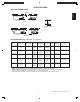
SPECIFICATIONS ENGLISH SPECIFICATIONS (Rectangular) MODEL BELLAVISTA™ 5 DIMENSIONS RH = RIGHT HAND DRAIN/OVERFLOW RH ELARA™ 6636 RH ELARA™ 7242 RH PRODUCT WEIGHT SKIRT & MOUNTING HEATER 20” (508 mm) A 11-3/4” (298 mm) B Template Provided P/N P187000 1025 lb (466 kg)/ 59 lb/ft2 (287 kg/m2) 80 U.S. gal (303 liters) 157 lb (71.
SPECIFICATIONS OVAL AND ROUND BATHS (13 mm) 1/2" W (Blower) H (Inlet Heater) ENGLISH L (Motor) SIDE VIEW END VIEW DUETTA A B (51 mm) 2" L DRAIN/OVERFLOW W H (Inlet Heater) (Blower) SIDE VIEW (Motor) END VIEW VENICIA™ SPECIFICATIONS (Oval and Round) MODEL DUETTA™ 6042 RH DUETTA™ 6636 RH DUETTA™ 6642 RH DUETTA™ 7242 RH VENICIA™ RH DIMENSIONS DRAIN/OVERFLOW RH = RIGHT HAND CUTOUT TOTAL WEIGHT/ FLOOR LOADING OPERATING GALLONAGE PRODUCT WEIGHT SKIRT & MOUNTING Min - 77 U.S.
SPECIFICATIONS ENGLISH CORNER BATHS 60" 25" 2” (51 mm) (Inlet Heater) (Blower) (Motor) SIDE VIEW END VIEW B DRAIN/OVERFLOW BELLAVISTA™ CORNER (159 mm) 6-1/4" 66" 66" 25-1/4" (Intake Heater) (Motor) A B (Blower) DRAIN/OVERFLOW END VIEW SIDE VIEW FUZION™ 6666 with wood (127 mm) 5" 66" 66" 24" (Motor) (Inlet Heater) A A B (Blower) DRAIN/OVERFLOW END VIEW SIDE VIEW FUZION™ 6666 undermount SPECIFICATIONS (Corner) RH = RIGHT HAND DRAIN/OVERFLOW CUTOUT TOTAL WEIGHT/ FLOOR LOADING O
ROUGHING-IN REFERENCE Some tubs are supplied with cutout template and/or undermount template. Refer to CUTOUT on pages 6-8 for template part numbers. 12" H x 24" L Service Access 30-1/8" Blower 4" x 4" 42" 12" H x 24" L Service Access 66" 30-1/8" Blower 4" x 4" 42" Motor Heater Motor Heater 11-3/4" 7" 6" 11-3/4" 32-1/2" 10" 6" Bellavista™ 5, 35-1/2" Bellavista™ 5.
ROUGHING-IN REFERENCE Some tubs are supplied with cutout template and/or undermount template. Refer to CUTOUT on pages 6-8 for template part numbers. ENGLISH 70-11/16'' 70-11/16'' Blower Blower 17-11/16'' 12'' x 4"* Motor 35-3/8'' 17-11/16'' Opt. Service Access 12" H x 24" L Service Access Motor 35-3/8'' Heater 2'' Fuzion™ 7236, Right Hand 12" H x 24" L Service Access 7'' 12'' x 4"* Heater 10-1/4'' Opt.
ROUGHING-IN REFERENCE Some tubs are supplied with cutout template and/or undermount template. Refer to CUTOUT on pages 6-8 for template part numbers. NOTE: On oval tubs the motor and blower mounting plates extend beyond the bath rim. ENGLISH 60" 66" Blower Motor 13" x 4" 42" 3.84" 30" Heater 2" 2" 13" x 4" 36" 3.84" 33" 11.04" Motor Heater 11.
ROUGHING-IN REFERENCE ENGLISH Some tubs are supplied with cutout template and/or undermount template. Refer to CUTOUT on pages 6-8 for template part numbers. 60" Blower 60" 12" H x 24" L Service Access 34-9/16" 59-1/2" Ref. 12" x 4"* Motor Heater 7.5" 3" 77-3/4" Opt. Service Access Corner Bath Cutout 40.94" 40.94" 67-1/2" Ref. 66" 69.68" Ref. 65" 65" 66" Blower 20" X 4" 9.29" Drain 32" 37.23" 32" 32.97" 32.97" Heater Motor 48" 12" H x 24" L Service Access 46.
INSTALLATION Framing and Support TYPICAL INSTALLATIONS MORTAR OR ADHESIVE MORTAR OR ADHESIVE TILE TILE SEALANT SEALANT ANCHOR STRAP FLASHING NAIL OR SCREW THROUGH ANCHOR STRAP INTO FLOOR FLOOR SUB-FLOOR FLASHING 1" X 4" (NOT FOR SUPPORT) FLUSH TO WALL 1" X 4" (NOT FOR SUPPORT) SEMI-SUNKEN Service Access PUMP/MOTOR & BLOWER SERVICE ACCESS - REQUIRED For partially or fully sunken installations, allow for access to service connections.
INSTALLATION ENGLISH Electrical Connections PUMP/MOTOR AND HEATER (Except Mito™ 6) Two (2) separate Ground Fault Circuit Interrupter (GFCI) are required for the Salon™ Spa units (except Mito™ 6). The Mito™ 6 requires a single Ground Fault Circuit Interrupter (GFCI). Electrical connections should be performed by a licensed electrician. Install a 240 VAC, 20 AMP RATED GFCI single outlet to the studwall underneath the bathtub, at least 4 inches (10,2 cm) above the floor. The single outlet is not provided.
Electrical Connections (continued) PUMP/MOTOR AND BLOWER FOR MITO™ 6 Install a 120 VAC, 20 AMP RATED GFCI single outlet to the studwall underneath the bathtub, at least 4 inches (10,2 cm) above the floor. The single outlet is not provided. A supplied power cord from the junction box with a 120 VAC plug connects to the customer supplied GFCI dedicated circuit. At initial start-up and before each use thereafter with power ON, push the GFCI test button. The reset button should pop out.
ENGLISH Plumbing and Water Supply Drain Information Fuzion™ Overflow Fitting Installation A drain/overflow assembly (sold separately) must be installed on the bath, water tested, and connected to the sanitary system of the house. After opening the carton, inspect for damage and verify that the kit is of the proper finish.
OPERATING INSTRUCTIONS Operation Water Level Close the drain and fill the bath until water is at least 1" to 2" (25,4 to 50,8 mm) above the highest jet (see water line indicated in the illustration). Do not turn on the whirlpool system at any time if the jets are not completely immersed in water. Running the whirlpool system when there is insufficient water in the bath could result in water spraying outside the bath area. Running the whirlpool system without water will damage the recirculating pump.
ENGLISH CONTROL PANEL OPERATION (WHIRLPOOL AND AIR BATH) [EXCEPT MITO™ 6] Electronic Control Panel Operation (with standard Chromatherapy lighting) All tubs in this product line (except the Mito™ 6) come with electronic controls and standard Chromatherapy lighting. Read and follow the operation instructions for the control system of your unit. General Functions This Jacuzzi tub is equipped with a eight button electronic control panel.
Left Air Valve Bath Light Right Air Valve Left Air Valve Status LEDs Pump/Motor Status LEDs ENGLISH Right Air Valve Status LEDs Blower Status LEDs ON/OFF Pump/Motor Wave Function Air Bath Toggle Switches Normal Operation (with the bath filled to the proper level) Pump/Motor Switch (ON/OFF ) Wave Function Switch (ON/OFF ) Pressing the button will turn ON the two speed pump/ motor at HIGH speed. Pressing a second time will turn OFF the pump/motor. To change speeds use the Toggle buttons.
CONTROL PANEL OPERATION (WHIRLPOOL AND AIR BATH FOR MITO™ 6] ENGLISH The Mito™ 6 has two control panels, one Air Bath and one Whirlpool. Control Panel Operation, Mito™ 6 Air Bath Controls General Functions Normal Mode: Press this button to turn the blower ON. The blower will be on for 20 minutes. The intensity may be changed by using either the up arrow button or the down arrow button. Pressing this button a second time will turn the blower OFF.
RapidHeat™ After the electronic controls are set, the whirlpool action in your bath can be influenced by up to three additional factors – direction of flow, force of water, and (whirlpool jet) force of air. All baths manufactured by Jacuzzi Whirlpool Bath are equipped with fully adjustable or partially adjustable jets, which are adjustable for one or more of these factors. Some baths have only directionally adjustable jets which can be adjusted for direction and flow of air only.
ENGLISH MAINTENANCE INSTRUCTIONS Cleaning the Bath Bath Additives To clean your bath, simply use a mild, nonabrasive liquid detergent solution. You can protect and restore the gloss to a dulled acrylic surface by applying Meguiar's #10 Mirror Glaze, a product specifically designed for use on acrylic finishes. If Meguiar's is not available, an acrylic polish of equal quality or automotive paste wax is acceptable. Never use abrasive household cleaners on any Jacuzzi Whirlpool Bath product.
MAINTENANCE INSTRUCTIONS Lamp Minor scratches which do not penetrate the color finish can be removed by lightly sanding with 600-grit wet/dry sandpaper. Restore the gloss using Meguiar's Mirror Glaze a product specifically designed for use on acrylic finishes. If Meguiar's is not available, an acrylic polish of equal quality or automotive paste wax is acceptable. Never use abrasive household cleaners on any Jacuzzi Whirlpool Bath product.
General Whirlpool Bath Troubleshooting Guide ENGLISH PROBLEM PROBABLE CAUSES Pump/Motor does not start. REMEDY No power to pump/motor. Reset GFCI. Pump/motor not plugged in. Insert plug fully into outlet. Pump/motor faulty. Replace pump/motor assembly. Jets are closed. Open jets by rotate counterclockwise. Suction cover/strainer may be clogged. With motor turned OFF, remove suction cover/strainer and remove any debris. Replace suction cover before operating.
AUTHORIZED SERVICE Electrical or Mechanical Repairs visit http://jacuzzi.com/pdf/ASA.PDF Finish, Surface, or Shell-Related Repairs visit http://jacuzzi.com/pdf/AFC.PDF Repair Parts or Accessories visit http://jacuzzi.com/pdf/MPD.PDF When requesting service or technical assistance please have available both the model and serial number of your unit. This information can be obtained from the product registration card provided with your unit.
ENGLISH THIS PAGE LEFT BLANK. PRODUCT SPECIFICATIONS ARE SUBJECT TO CHANGE WITHOUT NOTICE. USE INSTALLATION INSTRUCTIONS SUPPLIED WITH PRODUCT. Jacuzzi Whirlpool Bath has obtained applicable code (standards) listings generally available on a national basis for products of this type. It is the responsibility of the installer/owner to determine specific local code compliance prior to installation of the product.
Jacuzzi Whirlpool Bath Limited Warranty Salon™ Spa Air Bath and Whirlpool Product WARRANTY COVERAGE Jacuzzi Whirlpool Bath (the “Company”) offers the following express limited warranty to the original purchaser of any Jacuzzi Whirlpool Bath Designer Collection Bath Product (“unit”) who purchases the product for personal or single family use (“user”). The Company will repair or replace, at its option, the unit or its equipment in accordance with the following terms and conditions.
RESPONSIBILITIES OF OTHERS Inspecting the unit prior to installation is the responsibility of the installer or building contractor who acts on behalf of the user. They are responsible for ensuring the unit is free of defect or damage. Notices are placed on and in the unit and on the shipping carton advising the installer of this responsibility. In the event of a problem, the unit must not be installed.