Owner’s manual J-400™ J - 460 J - 465 J - 470 J - 480 2530-442U Rev.
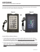
ADDENDUM Jacuzzi J-400 Series Owners Manual, #2530-442U Your new hot tub includes one of two stereo remote styles. Both remotes function 100% identically and contain only minor cosmetic differences outlined below: Style A Style B = 2 2 1 1 = Cosmetic Differences Between Remotes 1. The hand held remote provides you the ability to select the light system color mode. Remote Style A includes a light “MODE” Button.
Attention New Spa Owner! Congratulations on the purchase of your new Jacuzzi® spa! The following is a list of automated functions performed by your spa. These functions are listed below in an attempt to suppress any operational concerns you may have during the first 24 hours of ownership! Also listed below are important maintenance recommendations you should observe on a regular basis to protect your new investment.
Table of Contents 1.0 Important Spa Owner Information ��������������������������������������������������������� 1 2.0 2.1 FCC Notice ����������������������������������������������������������������������������������������������� 1 Industry Canada (IC) Information............................................................... 1 3.0 3.1 3.2 3.3 Important Safety Instructions for all Spa Owners �������������������������������� 2 Entrapment Risk...............................................................
11.0 11.1 11.2 11.3 11.4 Heating Modes ��������������������������������������������������������������������������������������� 37 Standard Mode (Factory Default)............................................................. 37 Economy Mode........................................................................................ 37 Selecting Standard or Economy Mode..................................................... 37 Clean-Up “Blow-Out” Cycle.................................................................
J-400 Series 1.0 Important Spa Owner Information Your Jacuzzi® spa is constructed to the highest standards and is capable of providing many years of trouble-free use. However, because heat retentive materials are utilized to insulate the spa for efficient operation, an uncovered spa surface directly exposed to sunlight and high temperatures for an extended period is subject to permanent damage. Damage caused by exposing the spa to this abuse is not covered under warranty.
J-400 Series 3.0 Important Safety Instructions for all Spa Owners READ AND FOLLOW ALL INSTRUCTIONS CAREFULLY! This spa was manufactured to meet the standards and specifications outlined in the “Virginia Graeme Baker Pool and Spa Safety Act” (VGB Safety Act). When installing and using this spa, basic safety precautions should always be followed, including: ! DANGER: Risk of Severe Injury or Drowning! 1. • Extreme caution must be exercised to prevent unauthorized access by children.
J-400 Series • • • • • • on the grounding lug, inside the equipment compartment on the equipment box. A grounding wire connector is provided on this unit to connect a minimum No. 8 AWG (8.4 mm²) solid copper conductor between this unit and any metal equipment, metal enclosures of electrical equipment, metal water pipe, or conduit within 5 feet (1.5m) of the unit. Never permit any electrical appliance, such as a light, telephone, radio, television, etc. within 5 feet (1.
J-400 Series ! WARNING: Risk of Severe Injury or Death! 6. • Since excessive water temperatures have a high potential for causing fetal damage during the early months of pregnancy, if pregnant or possibly pregnant, consult your physician before using a spa. • Pregnant or possibly pregnant women should limit spa water temperatures to 100°F (38°C).
J-400 Series 9. CAUTION: To DECREASE Risk of Product Damage. • Maintain water chemistry in accordance with manufacturer’s instructions. • Proper chemical maintenance of spa water is necessary to maintain safe water and prevent possible damage to spa components. 10. NOTE: This spa is not intended nor designed to be used in a commercial or public application.
J-400 Series 3.1 Entrapment Risk The Consumer Products Safety Commission/USA has reported that users of pools and spas have become entrapped (stuck) to drain and/or suction fittings causing death, drowning, or serious injury (see diagram below). This spa was manufactured to meet the standards and specifications outlined in the “Virginia Graeme Baker Pool and Spa Safety Act” (VGB Safety Act). Entrapment risk can be minimized if proper precautions are taken.
J-400 Series 3. • DANGER: Risk of Severe Injury or Drowning! Body entrapment: May occur when part of the torso becomes entrapped, inserted or sucked into a suction or outlet opening. Never allow children to play or get near the suction fittings, suction covers, filter, filter lid or skimmer assembly. ! ! DANGER: Risk of Severe Injury or Drowning! 4. Evisceration (disembowelment) entrapment: May occur when the buttocks becomes entrapped, inserted or sucked into a suction or outlet opening.
J-400 Series 3.3 Important CSA safety instructions (Canada only) When using this electrical equipment, basic safety precautions should always be followed, including the following: 1. READ AND FOLLOW ALL INSTRUCTIONS. 2. A green colored terminal or a terminal marked G, Gr, Ground, Grounding or the symbol* is located inside the supply terminal box or compartment.
J-400 Series ! WARNING: For spas that are to rest on balconies, roofs or other platforms not specifically tied into main structural support, consult a professional Structural Engineer with experience in this type of application. The spa must be installed in such a manner as to provide drainage away from it. Placing the spa in a depression without provisions for proper drainage could allow rain, overflow and other casual water to flood the equipment and create a wet condition in which it would sit in.
J-400 Series 4.2 Indoor Location For indoor installations many factors need to be considered before installing a spa indoors. • Proper Foundation: Consult a Structural Engineer when considering a foundation that will adequately support the spa the entire time it is in place. Proper support is critical especially if the spa is to rest on a second story or higher.
J-400 Series 5.0 General Electrical Safety Instructions Your new Jacuzzi® spa is equipped with the J-1000™ system. It contains the most advanced safety and selfprotective equipment in the industry. Nonetheless, this spa must be installed properly to ensure dependable usage. Please contact your local Jacuzzi dealer or local building department should you have any questions regarding your installation. Proper grounding is extremely important. Jacuzzi spas are equipped with a current collector system.
J-400 Series • • All wiring must be copper to ensure proper connections. Do not use aluminum wire. When using wire larger than #6 (10 mm²), add a junction box near the spa and reduce to short lengths of #8 (8.4 mm²) wire to connect to the spa. 4. The electrical supply for this product must include a suitably rated switch or circuit breaker to open all ungrounded supply conductors to comply with Section 422-20 of the National Electrical Code/USA, ANSI/NFPA 70.
J-400 Series Figure A Equipment Area 11 Flow 10 9 6 8 4 7 2 5 1. 2. 3. 4. 5. 6. 6 1 Note: Pump Locations Vary by Model Control Box Power Supply Entrance(s) Jet Pump #1 Heater Spa Drain Valve Pump Drain Plugs(s) 3 6 2 7. 8. 9. Jets Pump #2 Filter/Circulation Pump Optional CD Ozonator (Purchase Separately) 10. Factory Installed Ozone Injector 11. Control Panel Figure B Control Box 2 TB1 1 3 1. 2. 3.
J-400 Series RED RED TB1 1 1 BLK BLK Power In TB1 Figure-D RED BLK 2 to Circuit Board Green BLUE BLUE BROWN BROWN Power In Figure-C TB3 All North American 240V Models: 240 VAC, 3-Wire Connection 60 Hz 2 Green to Circuit Board TB3 All Export Models: 230 VAC, 3-Wire Connection 50 Hz 7.0 Power Requirements Jacuzzi® spas are designed to provide optimum performance and flexibility of use when connected to their maximum electrical service. They are configured at the factory.
J-400 Series Export J-460/J-465/J-470/J-480 Models (50Hz) Voltage: Max. Current Draw: Frequency: Number of Wires: Circuit Breaker (2-Pole): 230 VAC 230 VAC 230 VAC 16A 21A 29A 50 Hz 50 Hz 50 Hz 3 3 3 20A* 30A** 40A*** In 20A configuration, the heater will not operate while either jets pump is running. ** In 30A configuration, the heater will not operate while both jets pumps are running. This is the factory setting.
J-400 Series • ! WARNING: to decrease RISK OF infection or disease. Fill hot tub with clean tap water from garden hose, to reduce risk of contracting a waterborne illness (e.g. an infection, bacteria or virus) and/or respiratory ailments. Fill until water covers all jets but does not touch the bottom of the lowest headrest. (DO NOT OVERFILL!) IMPORTANT: Always fill your spa through both filter buckets after draining.
J-400 Series 7. Set Spa To Heat To warm spa water to a comfortable temperature, follow these steps: • The LCD display on the control panel displays the actual temperature of the spa water. Press either the COOLER or WARMER button once to display the “set” temperature for 5 seconds. If you want the water to heat to a different temperature, simply press COOLER or WARMER within 5 seconds. The set temperature increases or decreases by one degree each time either buttons is pressed.
J-400 Series 1. Add 2.5 ounces of sodium dichlor for every 100 gallons of water. Refer to the table below for approximate water fill volume by model. ! CAUTION: Risk of PERSONAL injury OR SPA DAMAGE! Never add chlorine tablets (trichlor) or acid to your hot tub for any reason! These chemical may damage components within your hot tub, burn or irritate your skin, create a rash, and void the manufacturer warranty for your spa.
J-400 Series CAUTION: TO DECREASE BUILD UP ON COMPONENTS AND MINIMIZE ACRYLIC DAMAGE. Never fill with water from a water softener. If your water is extremely “hard”, it is preferable to fill half-way with hard water and the rest of the way with softened water. You may fill entirely with hard water if you use a special water additive available from your Jacuzzi dealer. 5.
J-400 Series 9.0 Control Functions 9.1 Control Panel C D E B A. Select Button: Filter A cycle programming J features. Pressing the select button I also allows you H F G to turn on/off the circulation pump, Display shown for example purposes only, when it is in an off state. actual water temperature will vary. If the circulation pump was turned on automatically, it cannot be manually turned off. AM PM STANDARD B. Cycle cycle.
J-400 Series 9.2 LCD Display = Lock: Indicates panel, set temperature, or filter cycle programming is locked. = Heat: Indicates heater is on. AM PM STANDARD = Ozone: Indicates optional CD ozonator is on. = Adjust Filter Cycle: Indicates filter cycle programming feature is accessed. = Filter Cycle Number: Indicates which programmed filter cycle is running. = Filter Cycle: Indicates programmed filter cycle is running. = Filter Cycle Start Time: Indicates filter cycle start time programming is accessed.
J-400 Series 9.3 J-480 Spa Features 8 5 5 13 14 12 4 4 19 6 6 3 3 20 18 11 21 21 17 17 22 10 21 23 20 7 21 15 17 7 6 6 16 9 5 4 3 2 25 24 3 5 4 1 Spa features subject to change without notice. 1. Control Panel 2. Waterfall Control Valve 3. Air Control Valves (4 ea.) Introduce Air to Specified Jet Groups (Page 30) 4. Optional Audio System Speakers (4 ea.) 5. Adjustable Pillows (4 ea.) 6. Lighted Cup Holders (4 ea.) 7. Massage Selectors (2 ea.
J-400 Series 9.4 J-470 Spa Features 8 5 5 13 14 12 4 4 6 3 19 6 3 20 18 21 11 21 17 15 17 22 10 21 21 17 7 23 7 6 6 16 9 26 5 5 4 3 2 1 24 3 4 25 Spa features subject to change without notice. 1. Control Panel 2. Waterfall Control Valve 3. Air Control Valves (4 ea.) Introduce Air to Specified Jet Groups (Page 32) 4. Optional Audio System Speakers (4 ea.) 5. Adjustable Pillows (4 ea.) 6. Lighted Cup Holders (4 ea.) 7. Massage Selectors (2 ea.
J-400 Series 9.5 J-465 Spa Features 8 5 14 5 15 9 17 4 4 3 3 21 7 11 12 13 18 18 12 19 12 6 5 15 10 20 6 9 15 16 17 5 9 17 4 2 6 23 22 3 4 1 Spa features subject to change without notice. 1. Control Panel 2. Waterfall Control Valve 3. Air Control Valves (3 ea.) Introduce Air to Specified Jet Groups (Page 34) 4. Optional Audio System Speakers (4 ea.) 5. Adjustable Pillows (4 ea.) 6. Lighted Cup Holders (3 ea.) 7. Massage Selectors (1 ea.
J-400 Series 9.6 J-460 Spa Features 8 5 5 10 9 14 4 4 3 3 16 7 19 17 13 14 12 13 15 11 14 16 3 16 18 3 6 6 4 10 9 4 10 9 9 9 9 5 2 1 20 5 21 Spa features subject to change without notice. 1. Control Panel 2. Waterfall Control Valve 3. Air Control Valves (4 ea.) Introduce Air to Specified Jet Groups (Page 36) 4. Optional Audio System Speakers (4 ea.) 5. Adjustable Pillows (4 ea.) 6. Lighted Cup Holders (2 ea.) 7. Massage Selector (1 ea.
J-400 Series 10.0 Operating Instructions Your Jacuzzi® spa has a touch-sensitive control panel, massage selectors, and air control knobs located on the top rim of the spa (pages 22-25). These controls let you operate many of the special functions of your Jacuzzi spa. By familiarizing yourself with the following information, you will be able to gain the full benefit from using your spa . 10.
J-400 Series 10.6 Light Mode Button This button offers 4 light modes for your enjoyment. Press this button to select your favorite lighting effect as follows: Press Once Press Again Press Again High-Speed Color Blend Mode: Displays hundreds of colors in 5 second intervals. Low-Speed Color Blend Mode: Displays hundreds of colors in 20 seconds intervals. Freeze Color Blend Mode: Selects or “freezes” your low speed blending color of choice.
J-400 Series 10.10 WaterColour™ Waterfall Control Turn waterfall control valve (pages 29-36) counterclockwise to increase waterfall output. Turn control valve clockwise to decrease or turn off waterfalls. 10.11 Air Controls Certain jet systems have their own air control. Each control introduces air into the water lines that supply that specific jet group (pages 29-36). Simply rotate any air control clockwise to open or rotate counterclockwise to close.
J-400 Series 10.13 J-480 Massage/Waterfall Selector Diagram 3 5 2b 1b 2b 5 2a 4 2a 5 1 2 1a 1a 2a 3 4 Spa operation subject to change without notice. Massage Selectors (1-2) • Massage selector 1 diverts pump 2 output between jets groups 1a-1b. • Massage selector 2 diverts pump 1 output between jet groups 2a-2b. Waterfall Selector (3) • Waterfall selector 3 controls circulation pump output to waterfalls. Massage Selector (4) • Massage selector 4 controls pump 1 output to footwell IX Jet.
J-400 Series 10.14 J-480 Air Controls Diagram 2 3 2 2 3 3 4 2 4 2 1 4 1 4 4 1 4 Spa operation subject to change without notice. Air Controls Operation • Rotate air controls 1-4 to add air to designated jet groups. • Center footwell IX Jet draws air at all times when jets pump 1 is running. This jet has no air control.
J-400 Series 10.15 J-470 Massage/Waterfall Selector Diagram 3 5 2b 1b 2b 5 2a 4 5 2 1 2a 1a 3 4 Spa operation subject to change without notice. Massage Selectors (1-2) • Massage selector 1 diverts pump 2 output between jets groups 1a-1b. • Massage selector 2 diverts pump 1 output between jet groups 2a-2b. Waterfall Selector (3) • Waterfall selector 3 controls circulation pump output to waterfalls. Massage Selector (4) • Massage selector 4 controls pump 1 output to footwell IX Jet.
J-400 Series 10.16 J-470 Air Controls Diagram 1 3 2 2 3 3 1 4 1 4 1 1 4 Spa operation subject to change without notice. Air Controls Operation • Rotate air controls 1-4 to add air to designated jet groups. • Center footwell IX Jet draws air at all times when jets pump 1 is running. This jet has no air control.
J-400 Series 10.17 J-465 Massage/Waterfall Selector Diagram 3 4 1a 4 1 4 4 1b 2 4 1b 1b 3 2 Spa operation subject to change without notice. Massage Selectors (1) • Massage selector 1 diverts pump 1 output between jets groups 1a-1b. Massage Selector (2) • Massage selector 2 controls pump 1 output to footwell IX Jet. Waterfall Selector (3) • Waterfall selector 3 controls circulation pump output to waterfall.
J-400 Series 10.18 J-465 Air Controls Diagram 2 1 2 1 2 2 2 3 1 2 3 3 3 Spa operation subject to change without notice. Air Controls Operation • Rotate air controls 1-3 to add air to designated jet groups.
J-400 Series 10.19 J-460 Massage/Waterfall Selector Diagram 3 4 1b 4 1 4 L 1a 2 K 4 4 1a 3 2 Spa operation subject to change without notice. Massage Selector (1) • Massage selector 1 diverts pump 1 output between jets groups 1a-1b. Massage Selector (2) • Massage selector 2 controls pump 1 output to footwell IX Jet. Waterfall Selector (3) • Waterfall selector 3 controls circulation pump output to waterfall.
J-400 Series 10.20 J-460 Air Controls Diagram 4 1 4 1 4 3 L 2 5 K 3 2 3 3 2 Spa operation subject to change without notice. Air Controls Operation • Rotate air controls 1-4 to add air to designated jet groups. • Center footwell IX Jet (5) draws air at all times when jets pump 1 is running. This jet has no air control.
J-400 Series 11.0 Heating Modes The control system in your spa activates a programmable “standard” or “economy” mode which effects when the heater operates. Refer to sections 11.1 and 11.2 below for additional information. 11.1 Standard Mode (Factory Default) Standard mode is typically selected by customers in cold climates where heat up times are extended due to lower ambient temperatures.
J-400 Series 12.0 Programming Instructions 12.1 Programming Filter/Circulation Pump Run Time The Sentry control system allows you to easily adjust two separate aspects of filter/circulation pump operation: 1. The time of day (start time) the filter/circulation pump turns on. 2. The length of time (duration) the filter/circulation pump operates. The factory default start time is 12:00AM (Midnight). The default duration button to is 24 hours.
J-400 Series When in a Summer Logic condition is active (see note below), the filter/ circulation pump will turn on for all programmed filter cycles. Summer Logic: In warm weather, the water temperature in the spa may exceed the set temperature. This condition may occur due to heat transference from the filter/circulation pump and jets pumps.
J-400 Series When a programmed filter/heating cycle activates, the LCD screen displays the following message: 1* *Note: Number will vary according to which filter cycle is being programmed. At any time, you may check the programming of any aspect of any filter/ heating cycle by first pressing CYCLE button then moving through or SELECT button. The the menu by pressing either CYCLE programming is changed only by pressing WARMER or COOLER buttons during this process. 12.
J-400 Series 12.5 Locking Filter Cycles You may keep all filter cycle programs from being inadvertently altered by electronically “locking” them. • button, then To Lock All Filter Cycles: Press CYCLE , MODE and within 30 seconds, press DISPLAY LOCKED WARMER buttons within five seconds each. A padlock symbol will appear on the screen. In this state, the status of the cycle program may be checked, but may not be altered.
J-400 Series Programming Instructions button 2 times. The main display reads “FIL” 1. Press the CYCLE indicating the “Change Filter” display program has been accessed. button once to display the currently 2. Press SELECT programmed duration or to view days elapsed since last filter cleaning interval. or COOLER button to change duration 3.
J-400 Series 13.0 Spa Maintenance Proper and regular maintenance of your spa will help it retain its beauty and performance. Your authorized Jacuzzi dealer can supply you with all the information, supplies, and accessory products you will need to accomplish this.
J-400 Series To ensure optimum performance, the 24-hour ProClear™ II skimming filter cartridge (A) must be cleaned every three C months and replaced once a year. The secondary ProClear™ Plus polishing filter bag (B) should be emptied A weekly and replaced every 3 months. The ProClear™ II B filter cartridge (C) must be cleaned every three months and replaced once a year. To accomplish this, refer to the following filter cleaning procedure.
J-400 Series 6. Clean the ProClear filter cartridges with a garden hose and high pressure nozzle. Rinse debris from the filter pleats beginning at the top and working your way downward. Continue, one section at a time until you have cleaned all debris from the filter pleats. When replacing the filter cartridge, make sure you remove the center cap and chemical dispenser for use with the new cartridge. Replacement filter cartridges may be purchased from your authorized Jacuzzi dealer. 13.
J-400 Series 5. Pull the larger (rear) body outward as shown to open drain. 5. 6. After the spa drains, perform steps 2-5 in reverse order to close the drain prior to refilling spa. Open Drain After refilling, turn on power to the spa and follow the steps listed under “Spa Fill Up Procedures.” (page 15). Always fill your spa through both filter buckets. 13.
J-400 Series against deterioration caused by UV rays from the sun. Never allow anyone to stand or sit on the cover, and avoid dragging it across rough surfaces. 13.7 Winterizing Your Jacuzzi spa is designed to automatically protect itself against freezing when operating properly. During periods of severe freezing temperatures, you should check periodically to be certain that the electrical supply to the spa has not been interrupted.
J-400 Series Consult your Jacuzzi dealer if you have any questions regarding winter use or winterizing. 13.8 Restarting Your Spa in Cold Weather If you want to start up your spa after it has sat empty for a time in freezing temperatures, be aware that the water remaining in certain sections of the piping may still be frozen. This situation will block water flow preventing the spa from operating properly and possibly damaging the equipment.
J-400 Series 14.0 Water Quality Maintenance To decrease the risk of contracting a waterborne illness (e.g. an infection, bacteria or virus) and/or respiratory ailments, maintain water quality within specified limits. This will enhance your enjoyment and prolong the life of the hot tub’s equipment. Doing so requires regular attention because the water chemistry involved is a balance of several factors.
J-400 Series When adding spa shock (chlorine or non-chlorine) or pH balancing chemicals activate the jets pump(s) and leave the spa cover open for a minimum of 20 minutes. By doing this you will allow excessive chemical vapors to exit the spa, protecting pillows and plastic knobs from chemical attack.
J-400 Series 15.0 Troubleshooting - Display Messages There are a number of unique functions designed into your Jacuzzi spa to protect it from damage and/or to aid in troubleshooting. Following is a listing of all the possible messages along with their meanings: MESSAGE MEANING Overheat Protection (Heater is deactivated, filter/ circulation pump is activated). ! WARNING: Risk of Hyperthermia (over-heating) Causing Severe Injury, burns, or welts. Water temperature is above acceptable limits.
J-400 Series FREEZE PROTECTION A potential freeze condition has been detected. No action is required. Jets pump(s) operate until the spa is out of danger. It is possible to manually turn off pump 1 and pump 2, but if after 2 hours ICE is still detected, pumps will automatically turn back on. Note: This error commonly occurs when the spa is first filled because tap water is often very cold. Communication between the control panel and/or remote control panel and circuit board is faulty.
J-400 Series 16.0 Troubleshooting - Procedures In the unlikely event your spa is not working the way you believe it should, please first review all the installation and operating instructions in this manual and check the message on the panel display; second, if you are still not satisfied it is working properly, please follow the appropriate troubleshooting instructions. PROBLEM PROCEDURE NONE OF THE COMPONENTS OPERATE (i.e. pump light) Check the control panel lights. 1.
J-400 Series POOR JET ACTION (see page 29-36) 1. 2. 3. 4. 5. Make certain the jets pump is turned on. Check position of massage selectors. Open air control for selected jet system. Check for adequate water level. Check for dirty filter (page 43). WATER IS TOO HOT 1. Reduce thermostat setting (page 17). 2. Switch hot tub to “Economy” mode to turn heater on only during programmed filter cycles (page 37). NO HEAT 1. Check thermostat setting. 2. Keep the cover in place while heating. 3.
! DANGER Turn power off before servicing. This task should only be performed by a qualified technician. Heater 5.5 kW TB3 GRN HI RED PUMP 2 WHT TB1 1 K4 HI RED K3 PUMP 1 WHT K2 1 3 5 7 9 11 13 1 3 5 7 9 3 External Service Panel Box - Disconnect Means Must Be Located No Closer Than 5FT (1.52 Meters) From Edge And Within Sight of Spa. K1 K13 J6 J8 JP20 Sensors Options JP9 RISK OF SHOCK OR ELECTROCUTION! 1 3 5 7 9 11 13 1 3 5 7 9 JP20 JP9 JP19 See Section 7.
Page 56 Turn power off before servicing. This task should only be performed by a qualified technician. RISK OF SHOCK OR ELECTROCUTION! DANGER Heater 5.
J-400 Series 19.0 Typical Spa Wiring Diagrams A-B (North American 60Hz Models Only) ! DANGER RISK OF SHOCK OR ELECTROCUTION! Turn power off before servicing. This task should only be performed by a qualified technician.
J-400 Series 20.0 Optional Jacuzzi J-1000 Audio System™ Stereo System Features 20.1 Sound System Controls 2 5 6 17 8 7 4 9 1 3 16 10 11 12 13 14 15 1. 2. 3. 4. 5. 6. 7. 8. 9. 10. Power On/Off Button Tune/Seek Up/Down Button Volume Up/Down Button Mode Button SEL/EQ Button AS/PS Button MUTE Button BAND/RPT Button ENT/SH/RDM Button USB Docking Station Page 58 11. 12. 13. 14. 15. 16. 17.
J-400 Series 20.2 Sound System Operation 1. Power On and Off Press power button (1) once to turn on stereo system. Press a second time to turn off. 2. Adjusting Volume Press VOL Up/Down button (3) to increase or decrease volume. Current volume setting is briefly displayed (0 to 45). 2 5 6 17 8 1 7 4 9 3 16 10 11 12 14 13 15 3. Mute In Radio or AUX mode, press mute button (7) once to mute audio output (“MUTE” appears on display).
J-400 Series 8. Adjusting Fader Level Press EQ button (5) repeatedly until display reads “FADER.” Press VOL Up/ Down button (3) to choose desired setting. A display of “FADER F-R” indicates center, R01 to 15 indicates rear fade, F01 to 15 indicates front fade. Note: Unit returns to volume mode if volume control is not operated for 3 seconds. 2 5 6 17 8 1 7 4 9 3 16 10 12 11 13 14 9.
J-400 Series 12. Open/Close Front Panel Press firmly on the release button (15), then open front panel (16) by gently lifting upward on bottom edge. To close front panel, gently flip panel down, then press firmly on panel directly above release button (15) until you hear an audible “click”. Keep front panel closed at all the times to prevent water intrusion, except when changing discs. CAUTION: Never insert wet discs into unit or CD player will be damage! 20.3 J-1000™ Audio System Radio Operation 1.
J-400 Series 5. Accessing Preset Stations Press and hold ENT/SH button (9) until display reads “SHIFT”. Repeatedly press TUN up or down button (2) to choose preset 1-6, then press ENT/SH button (9) to confirm selection. 20.4 J-1000™ Audio System CD Player Operation 2 5 6 17 8 1 7 4 9 3 16 10 11 12 14 13 1. Insert, Play, and Eject a CD 15 Open front panel (16) by pressing firmly on release button (15) and lifting panel upward from bottom edge. Gently insert CD into slot (14) with label facing up.
J-400 Series Press a second time to deactivate or press RDM button to cancel RPT function. 4. Searching File or Folder in MP3/WMA CD • To Search File in CDP (MP3/WMA) mode: Press AS/PS button (6) to enter track searching mode. Then press the VOL up/down button (3) to scroll through available tracks. At desired track, press ENT button (9) to confirm selection. Once a track is selected, it will automatically begin to play.
J-400 Series 2. Copying Music Files from USB to NAND (internal memory) 5 7 In USB mode, press and hold SEL 2 3 6 17 4 button (5) for about 2 seconds until 8 9 1 “ONE COPY” displays on LCD (17), then press VOL up or down button (3) 16 to choose ONE or ALL. Press ENT 10 button (9) to confirm selection. • If ONE COPY is selected: The record percent “DOWN LOAD xx%” will display on the LCD (17). After 11 12 copying is finished, the next track will 13 14 automatically begin playback.
J-400 Series 20.6 J-1000™ Audio System iPod Operation 1. Play iPod Open front panel (16) and plug a iPod into the iPod Docking Station (12) as shown. Refer to step 12 (page 61) for details. The iPod will begin to play automatically. Close front panel. The “iPod” symbol will display to indicate a iPod is connected. • To Play connected iPod: Press MODE button (4) to change to iPod mode. The iPod will play. The display shows current track, play time, and iPod symbol to indicate an iPod is connected.
J-400 Series 20.7 Docking your iPod Music Player 1. Docking Your iPod The Docking Station for iPod is compatible with all dockable Apple iPod models. To Install an Apple iPod: A. Open Docking Station door (A) as outlined in step 12 (page 61). B. Center iPod over Docking Station Interface Port, then gently press downward as shown (B). DO NOT FORCE! C. Close Docking Station door as shown (C), then press firmly on door directly above door release latch (15) until you hear an audible “click”.
J-400 Series 20.8 Generic MP3 Player Operation 1. Connecting Your MP3 Player A. The Audio unit is equipped with an auxiliary audio input jack, that allows the user to listen to external source, such as an MP3 Player. 2 5 6 17 8 1 7 4 9 3 16 10 2. Setting Up The MP3 Player for Use 11 12 A. Select preferred song/album/ playlist prior to plugging in MP3 13 14 player and start playback. B. Press “Mode Button” on stereo 15 receiver until the LCD display reads “AUX”.
J-400 Series 2. Fogged CDs and Lens This condition may occur when it’s cold. Wipe fogged CDs with a soft cloth. Fogged optical components inside the unit will return to normal operation after an hour in a heated environment. 20.10 J-1000™ Audio System Stereo Specifications Tuner FM usable sensitivity . . . . . . . . . . . . . . . . . . . . . . . . . . . . . . . . . . . . . FM 50dB quieting sensitivity . . . . . . . . . . . . . . . . . . . . . . . . . . . . . . . FM alternate channel selectivity . . . . . .
J-400 Series 20.11 Standard Wireless Remote Control (Included With Optional J-1000 Sound System) • • • Usable range 15' (5m) Never leave the remote under the spa cover for any reason. Battery Replacement: Use Coin Type, CR2025 or equivalent. Wireless Remote Control Command Summary Button Power Mute Source Operation Power Button: On/Off. Mute Button: On/Off. Source Button: Selects Radio, CD or iPod/MP3 Player function.
J-400 Series Button Operation Auto Button: Scans through preset radio stations. Auto Audio Button: Selects treble, bass, fader or balance, audio settings. Audio Band Button: Selects AM or FM band. Band Zone 1 Button Volume Buttons: Zone 1 buttons are used to adjust volume levels. Zone 2 buttons not used. Zone 2 Volume 4 5 Disc - 6 Disc + Tune Light Button: Turns spa light on/off (See Sec. 10.5, page 26) Light Mode Button: Selects one of four light modes (See Sec. 10.
J-400 Series 20.12 Wireless Remote Battery Replacement Procedure 1. Start by removing the rubber cover to the remote (Figure A). Fig. A 2. Turn the remote unit over and locate the battery door (Figure B). OPEN CLOSED Battery Door Fig. B OPEN CLOSED 3. Rotate the battery door, with a coin, counterclockwise until the dot aligns with the Open arrow (Figure C). Fig. C OPEN CLOSED 4. Remove battery door using coin to pry the door upward (Figure D). Fig. D OPEN 5.
J-400 Series Serial Number: _ ___________________________ Model Name: _ ___________________________ Dealer Name: _ ___________________________ Notes: ____________________________________ _________________________________________ _________________________________________ _________________________________________ Page 72