Owner’s manual J-400™ J - 460 J - 465 J - 470 J - 480 2530-442T Rev.
Attention New Spa Owner! Congratulations on the purchase of your new Jacuzzi® spa! The following is a list of automated functions performed by your spa. These functions are listed below in an attempt to suppress any operational concerns you may have during the first 24 hours of ownership! Also listed below are important maintenance recommendations you should observe on a regular basis to protect your new investment.
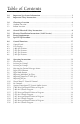
Table of Contents 1.0 2.0 Important Spa Owner Information ����������������������������������������������������������������1 Important Safety Instructions ������������������������������������������������������������������������2 3.0 3.1 3.2 Choosing a Location ��������������������������������������������������������������������������������������6 Outdoor Location.................................................................................................6 Indoor Location...............................
10.0 10.1 10.2 10.3 10.4 Heating Modes ���������������������������������������������������������������������������������������������34 Standard Mode (Factory Default)........................................................................34 Economy Mode..................................................................................................34 Selecting Standard or Economy Mode................................................................34 Clean-Up “Blow-Out” Cycle...............................
J-400 Series 1.0 Important Spa Owner Information Your Jacuzzi® spa is constructed to the highest standards and is capable of providing many years of trouble-free use. However, because heat retentive materials are utilized to insulate the spa for efficient operation, an uncovered spa surface directly exposed to sunlight and high temperatures for an extended period is subject to permanent damage. Damage caused by exposing the spa to this abuse is not covered under warranty.
J-400 Series 2.0 IMPORTANT SAFETY INSTRUCTIONS READ AND FOLLOW ALL INSTRUCTIONS CAREFULLY WHEN INSTALLING AND USING THIS ELECTRICAL EQUIPMENT, BASIC SAFETY PRECAUTIONS SHOULD ALWAYS BE FOLLOWED, INCLUDING: 1. Warning: To reduce the risk of injury, do not permit children to use this product unless they are closely supervised at all times. 2. Warning: A grounding wire connector is provided on this unit to connect a minimum No. 8 AWG (8.
J-400 Series 9. The water in a spa should never exceed 104°F (40°C). Water temperatures between 100°F (38°C) and 104°F (40°C) are considered safe for a healthy adult. Lower water temperatures are recommended for young children and when spa use exceeds 10 minutes. 10. Since excessive water temperatures have a high potential for causing fetal damage during the early months of pregnancy, pregnant or possibly pregnant women should limit spa water temperatures to 100°F (38°C).
J-400 Series *IEC Publication 417, Symbol 5019. 3. At least two lugs marked “Bonding Lugs” are provided on the external surface or on the inside of the supply terminal box/compartment. To reduce the risk of electric shock, connect the local common bonding grid in the area of the spa to these terminals with an insulated or bare copper conductor not smaller than No. 6 AWG (10mm²). 4.
J-400 Series CAUTION: Maintain water chemistry in accordance with manufacturer’s instructions. WARNING: The use of alcohol or drugs can greatly increase the risk of fatal hyperthermia in spas. SAVE THESE INSTRUCTIONS HYPERTHERMIA Prolonged immersion in hot water may induce hyperthermia. A description of the causes, symptoms, and effects of hyperthermia are as follows: Hyperthermia occurs when the internal temperature of the body reaches a level several degrees above the normal body temperature of 98.
J-400 Series 6. Never bring any electrical appliances into or near the spa. Never operate any electrical appliances from inside the spa or when you are wet unless such appliances are built-in by the manufacturer. 7. Proper chemical maintenance of spa water is necessary to maintain safe water and prevent possible damage to spa components. 8. Use the straps and clip tie downs to secure the cover when not in use.
J-400 Series • The overall enhancement of your environment. It is preferable not to place the spa under an unguttered roof overhang since run-off water will shorten the life expectancy of the spa cover. 3.2 Indoor Location For indoor installations many factors need to be considered before installing a spa indoors. • Proper Foundation: Consult a Structural Engineer when considering a foundation that will adequately support the spa the entire time it is in place.
J-400 Series WARNING: In addition to maintenance of filters and water chemistry, proper ventilation is recommended to reduce the risk of exposure to viruses and bacteria that could be present in the air or water. Consult a licensed architect or building contractor to determine your specific needs if installing your spa indoors. 4.0 General Electrical Safety Instructions Your new Jacuzzi® spa is equipped with the “state-of-the-art” Sentry™ equipment system.
J-400 Series 5.0 Electrical Installation Instructions (240V Service) IMPORTANT NOTICE: The electrical wiring of this spa must meet the requirements of the National Electrical Code/USA (NEC) and any applicable state or local codes. The electrical circuit must be installed by a qualified electrician and approved by a local building/electrical inspection authority. 1. This spa must be permanently connected (hard-wired) to the power supply.
J-400 Series 8. Connect wires, color to color, on terminal blocks TB1 and TB3 (Figure C-D, page 11). TIGHTEN SECURELY! All wires must be hooked up securely or damage could result. 9. Install control box door and reinstall the cabinet side panels. Figure A Equipment Area 11 Flow 10 9 6 8 4 7 2 5 1. 2. 3. 4. 5. 6. 6 1 Note: Pump Locations Vary by Model Control Box Power Supply Entrance(s) Jet Pump #1 Heater Spa Drain Valve Pump Drain Plugs(s) 7. 8. 9. 2 1 3 1. 2. 3.
J-400 Series RED TB1 1 Power In BLK 2 Green RED TB1 Figure-D RED 1 BLK BLK BLUE BLUE BROWN BROWN Power In Figure-C to Circuit Board TB3 All North American 240V Models: 120/240 VAC, 3-Wire Connection 60Hz 2 Green to Circuit Board TB3 All Export Models: 230 VAC, 3-Wire Connection 50Hz 6.0 Power Requirements Jacuzzi® spas are designed to provide optimum performance and flexibility of use when connected to their maximum electrical service. They are configured at the factory.
J-400 Series Export J-460/J-465/J-470/J-480 Models (50Hz) Voltage: 240VAC 240VAC 240VAC Max. Current Draw: 16A 21A 29A Frequency: 50Hz 50Hz 60Hz 3 3 3 20A* 30A** 40A*** Number of Wires: Circuit Breaker (2-Pole): In 20A configuration, the heater will not operate while either jets pump is running. ** In 30A configuration, the heater will not operate while both jets pumps are running. This is the factory setting.
J-400 Series • Fill spa until water level is above all jets and just touching the bottom of each headrest in its lowest position. DO NOT OVERFILL! IMPORTANT: Always fill your spa through both filter buckets after draining. Failure to do so may cause air to be trapped in either pump, preventing the pump from circulating water. Remove the hose and replace both filter cartridges as illustrated in section 12.1 (page 39). 3. Turn On Power Turn on power to spa at the home’s circuit breaker.
J-400 Series Important Heater Details: • The maximum temperature for which the spa can be set is 104°F (40°C) and the minimum is 80°F (27°C). • For North American spas powered by a service of less than 60 amps, turn off jets pump #1 and jets pump #2 to operate heater. • Setting the thermostat at maximum will not accelerate the heating process. This will only result in a higher ultimate temperature. • The heater operates until the water reaches 1 degree above the programmed “set temperature”, then turns off.
J-400 Series 2. Leave spa cover open during this step to allow excessive B C chemical vapors to exit spa, protecting pillows and plastic knobs from chemical attack. If spa is indoors, open doors and windows for proper ventilation. Turn on all spa jets A pumps for one hour, open all air controls, and place all massage selector knob(s) in their center “combo” position as shown (right).
J-400 Series CAUTION: Never leave your spa unattended for any reason while the cover is open and accessible to small children and animals! CAUTION: To prevent the unlikely possibility of contracting a waterborne illness, maintain water chemistry within step 6 parameters. If you or other bathers experience such a condition, discontinue use and seek medical attention. 7. Establish a sanitizer reading between 3.0-4.0 ppm chlorine or 2.0-4.0 ppm bromine, then allow the spa to set undisturbed for 8 hours.
J-400 Series 8.0 Control Functions 8.1 Control Panel C D E B A. Select Button: Filter A cycle programming features. Pressing the select I button also allows H F you to turn on/off G the circulation pump, when it is in an off state. If the circulation pump was turned on automatically, it cannot be manually turned off. AM PM STANDARD B. Cycle J Button: Accesses filter cycle program mode and next cycle. C. Mode Button: Switches between standard and economy filtration/ heating modes sections. D.
J-400 Series 8.2 LCD Display = Lock: Indicates panel, set temperature, or filter cycle programming is locked. AM PM = Heat: Indicates heater is on. = Ozone: Indicates optional CD ozonator is on. STANDARD *Display shown for example purposes only, actual water temperature will vary. = Adjust Filter Cycle: Indicates filter cycle programming feature is accessed. = Filter Cycle Number: Indicates which programmed filter cycle is running. = Filter Cycle: Indicates programmed filter cycle is running.
J-400 Series 8.3 J-480 Spa Features H E E M N L D D T F C F C U S K V V R R W J V U G V R X O G F F Q I E D C B Z A Y E C D P Spa features subject to change without notice. A. Control Panel B. Waterfall Control Valve C. Air Control Valves (4 ea.) Introduce Air to Specified Jet Groups (Page 27) D. Optional Audio System Speakers (4 ea.) E. Adjustable Pillows (4 ea.) F. Lighted Cup Holders (4 ea.) G. Massage Selectors (2 ea.) Controls Specified Jet Groups (Page 26) H.
J-400 Series 8.4 J-470 Spa Features H E E M N L D D F C S F C T R U K U Q U U W Q G O Q V J G F F P I Z E E D C B X A Y C D AA Spa features subject to change without notice. A. Control Panel B. Waterfall Control Valve C. Air Control Valves (4 ea.) Introduce Air to Specified Jet Groups (Page 29) D. Optional Audio System Speakers (4 ea.) E. Adjustable Pillows (4 ea.) F. Lighted Cup Holders (4 ea.) G. Massage Selectors (2 ea.) Controls Specified Jet Groups (Page 28). H.
J-400 Series 8.5 J-465 Spa Features H E N E O I Q D D C C U G K L M R R L S L F E O J T F Q I O P E I Q D B F V A D C X W Spa features subject to change without notice. A. Control Panel B. Waterfall Control Valve C. Air Control Valves (3 ea.) Introduce Air to Specified Jet Groups (Page 31) D. Optional Audio System Speakers (4 ea.) E. Adjustable Pillows (4 ea.) F. Lighted Cup Holders (3 ea.) G. Massage Selectors (1 ea.) Controls Specified Jet Groups (Page 30). H.
J-400 Series 8.6 J-460 Spa Features H E E J I N D D C C G S P Q M N L M O K N P C P R C F F D J I D J I I I I E B T A U E V Spa features subject to change without notice. A. Control Panel B. Waterfall Control Valve C. Air Control Valves (4 ea.) Introduce Air to Specified Jet Groups (Page 33) D. Optional Audio System Speakers (4 ea.) E. Adjustable Pillows (4 ea.) F. Lighted Cup Holders (2 ea.) G. Massage Selector (1 ea.) Controls Specified Jet Groups (Page 32). H.
J-400 Series 9.0 Operating Instructions Your Jacuzzi® spa has a touch-sensitive control panel, massage selectors, and air control knobs located on the top rim of the spa (page 19-22). These controls let you operate many of the special functions of your Jacuzzi spa. By familiarizing yourself with the following information, you will be able to gain the full benefit from using your spa . 9.
J-400 Series 9.6 Light Mode Button This button offers 5 light modes for your enjoyment. Press this button to select your favorite lighting effect as follows: Press Once Press Again Press Again High-Speed Color Blend Mode: Displays hundreds of colors in 5 second intervals. Low-Speed Color Blend Mode: Displays hundreds of colors in 20 seconds intervals. Freeze Color Blend Mode: Selects or “freezes” your low speed blending color of choice.
J-400 Series 9.8 Adjusting PowerPro™ MX2 Jets Tilt PowerPro MX2 Jet nozzle to angle of choice as desired. Rotate nozzle clockwise to reduce flow volume from jet or rotate counterclockwise to increase flow volume. Note: Always keep at least 6 adjustable jets open at all times. 9.9 Adjusting RX Jets Turn center jet adjustment knob clockwise to decrease or shut off water flow. Turn center jet adjustment knob counterclockwise to turn on or increase water flow.
J-400 Series 9.13 J-480 Massage/Waterfall Selector Diagram 3 5 2b 1b 2b 5 2a 4 2a 5 1 2 1a 1a 2a 3 4 Spa operation subject to change without notice. Massage Selectors (1-2) • Massage selector 1 diverts pump 2 output between jets groups 1a-1b. • Massage selector 2 diverts pump 1 output between jet groups 2a-2b. Waterfall Selector (3) • Waterfall selector 3 controls circulation pump output to waterfalls. Massage Selector (4) • Massage selector 4 controls pump 1 output to footwell IX Jet.
J-400 Series 9.14 J-480 Air Controls Diagram 2 3 2 2 3 3 4 2 4 2 1 4 1 4 4 1 4 Spa operation subject to change without notice. Air Controls Operation • Rotate air controls 1-4 to add air to designated jet groups. • Center footwell IX Jet draws air at all times when jets pump 1 is running. This jet has no air control.
J-400 Series 9.15 J-470 Massage/Waterfall Selector Diagram 3 5 2b 1b 2b 5 2a 4 5 2 1 2a 1a 3 4 Spa operation subject to change without notice. Massage Selectors (1-2) • Massage selector 1 diverts pump 2 output between jets groups 1a-1b. • Massage selector 2 diverts pump 1 output between jet groups 2a-2b. Waterfall Selector (3) • Waterfall selector 3 controls circulation pump output to waterfalls. Massage Selector (4) • Massage selector 4 controls pump 1 output to footwell IX Jet.
J-400 Series 9.16 J-470 Air Controls Diagram 1 3 2 2 3 3 1 4 1 4 1 1 4 Spa operation subject to change without notice. Air Controls Operation • Rotate air controls 1-4 to add air to designated jet groups. • Center footwell IX Jet draws air at all times when jets pump 1 is running. This jet has no air control.
J-400 Series 9.17 J-465 Massage/Waterfall Selector Diagram 3 4 1a 4 1 4 4 1b 2 4 1b 1b 3 2 Spa operation subject to change without notice. Massage Selectors (1) • Massage selector 1 diverts pump 1 output between jets groups 1a-1b. Massage Selector (2) • Massage selector 2 controls pump 1 output to footwell IX Jet. Waterfall Selector (3) • Waterfall selector 3 controls circulation pump output to waterfall.
J-400 Series 9.18 J-465 Air Controls Diagram 2 1 2 1 2 2 2 3 1 2 3 3 3 Spa operation subject to change without notice. Air Controls Operation • Rotate air controls 1-3 to add air to designated jet groups.
J-400 Series 9.19 J-460 Massage/Waterfall Selector Diagram 3 4 1b 4 1 4 L 1a 2 K 4 4 1a 3 2 Spa operation subject to change without notice. Massage Selector (1) • Massage selector 1 diverts pump 1 output between jets groups 1a-1b. Massage Selector (2) • Massage selector 2 controls pump 1 output to footwell IX Jet. Waterfall Selector (3) • Waterfall selector 3 controls circulation pump output to waterfall.
J-400 Series 9.20 J-460 Air Controls Diagram 4 1 4 1 4 3 L 2 5 K 3 2 3 3 2 Spa operation subject to change without notice. Air Controls Operation • Rotate air controls 1-4 to add air to designated jet groups. • Center footwell IX Jet (5) draws air at all times when jets pump 1 is running. This jet has no air control.
J-400 Series 10.0 Heating Modes The control system in your spa activates a programmable “standard” or “economy” mode which effects when the heater operates. Refer to sections 10.1 and 10.2 below for additional information. 10.1 Standard Mode (Factory Default) Standard mode is typically selected by customers in cold climates where heat up times are extended due to lower ambient temperatures.
J-400 Series 11.0 Programming Instructions 11.1 Programming Filter/Circulation Pump Run Time The Sentry control system allows you to easily adjust two separate aspects of filter/circulation pump operation: 1. 2. The time of day (start time) the filter/circulation pump turns on. The length of time (duration) the filter/circulation pump operates. The factory default start time is 12:00AM (Midnight). The default duration is 24 hours.
J-400 Series When in a Summer Logic condition is active (see note below), the filter/circulation pump will turn on for all programmed filter cycles. Summer Logic: In warm weather, the water temperature in the spa may exceed the set temperature. This condition may occur due to heat transference from the filter/circulation pump and jets pumps.
J-400 Series When a programmed filter/heating cycle activates, the LCD screen displays the following message: 1* *Note: Number will vary according to which filter cycle is being programmed. At any time, you may check the programming of any aspect of any filter/heating cycle by first pressing CYCLE button then moving through the menu by pressing either CYCLE or SELECT button. The programming is changed only by pressing WARMER or COOLER buttons during this process. 11.
J-400 Series 11.5 Locking Filter Cycles You may keep all filter cycle programs from being inadvertently altered by electronically “locking” them. • To Lock All Filter Cycles: Press CYCLE button, then within 30 seconds, press DISPLAY , MODE and WARMER buttons within five seconds each. A padlock symbol will appear on LOCKED the screen. In this state, the status of the cycle program may be checked, but may not be altered.
J-400 Series 3. 4. Press WARMER or COOLER button to change duration setting as follows: 0 - 10 - 20 - 30 - 40 - 50 - 60 - 70 - 80 - 90 - 100 - 110 - 120 - OFF Note: Selecting 0 in step 3 forces the change filter reminder icon to remain on indefinitely. Press DISPLAY button once to save changes and return to the standard water temperature display. Note: If no button is pressed within 30 seconds, all changes are recorded and the screen automatically returns to the standard water temperature display. 12.
J-400 Series ALWAYS TURN POWER TO THE SPA OFF BEFORE CLEANING THE FILTER CARTRIDGES! NEVER OPERATE SPA WITHOUT FILTER LID (2) AND SKIMMER ASSEMBLY (4) INSTALLED. A 1. 2. 3. 4. 5. B 1. 2. 3. 4. 5. 6. Remove power to the hot tub before removing the skimmer (A) or filter bag cover (B). Remove the polishing bag lid (B) by rotating it counterclockwise approximately 5 degrees until you feel it unlatch.
J-400 Series CAUTION! READ THIS BEFORE DRAINING: To prevent damage to the spas components, turn off power to the spa at the circuit breaker before draining it. Do not turn the power back on until your spa has been refilled. CAUTION: There are certain precautions to keep in mind when draining your spa. If it is extremely cold, and the spa is outdoors, freezing could occur in the lines or the equipment (see “WINTERIZING”, page 42).
J-400 Series assure that no soap residue is left on the surface. This could cause severe sudsing when the spa is refilled. 12.4 Pillow Care Clean the four headrests in your spa as needed by wiping them with a cloth with soapy water. It is not necessary to remove the headrests for cleaning. To remove headrests for long term storage or replacement, grasp both ends of each headrest and gently pull inward towards the center of the spa.
J-400 Series For expert winterization of your spa, contact your authorized Jacuzzi dealer. In emergency situations, damage can be minimized by taking the following steps: CAUTION: Turn off power to spa. 1. 2. 3. 4. 5. 6. Follow the directions on page 40 for draining the spa. As the water level drops below the seats, use whatever means necessary to get the water out of the recessed seating areas and into the footwell.
J-400 Series 13.0 Water Quality Maintenance Maintaining the quality of the water within specified limits will serve to enhance your enjoyment and prolong the life of the spa’s equipment. It is a fairly simple task, but it requires regular attention because the water chemistry involved is a balance of several factors. There is no simple formula, and there is no avoiding it.
J-400 Series 13.3 Other Additives Many other additives are available for your spa. Some are necessary to compensate for out-of-balance water, some aid in cosmetic water treatment and others simply alter the feel or smell of the water. Your Authorized Jacuzzi dealer can advise you on the use of these additives. 13.
J-400 Series Panel buttons have been pressed too many times in a short period of time. Because this could cause excessive wear on equipment components, panel buttons are temporarily deactivated. Panel buttons will automatically re-activate if no button is pressed for 30 seconds. Circuit board temperature has exceeded acceptable limit. This message will disappear when the circuit board temperature drops below acceptable limit. If condition persists, provide shade for equipment side of spa.
J-400 Series 15.0 Troubleshooting - Procedures In the unlikely event your spa is not working the way you believe it should, please first review all the installation and operating instructions in this manual and check the message on the panel display; second, if you are still not satisfied it is working properly, please follow the appropriate troubleshooting instructions. PROBLEM PROCEDURE NONE OF THE COMPONENTS OPERATE (i.e. pump light) Check the control panel lights. 1.
J-400 Series POOR JET ACTION (see page 26-33) 1. 2. 3. 4. 5. Make certain the jets pump is turned on. Check position of massage selectors. Open air control for selected jet system. Check for adequate water level. Check for dirty filter (page 39). WATER IS TOO HOT 1. 2. Reduce thermostat setting (page 13). Switch hot tub to “Economy” mode to turn heater on only during programmed filter cycles (page 34). NO HEAT 1. 2. 3. Check thermostat setting. Keep the cover in place while heating.
Not Used Not Used Not Used On enables 60A Logic On 2-Pump Logic, Off 1-Pump Logic On enables 30A Logic, Off enables 50A or 60A Logic Not used JP9-1: JP9-3: JP9-5: JP9-7: JP9-9: JP9-11: Caution: always remove power to spa before making jumper changes on the circuit board. Heater 5.5 kW GRN 3 External Service Panel Box - Disconnect Means Must Be Located No Closer Than 5FT (1.52 Meters) From Edge And Within Sight of Spa.
Page 50 Not Used Not Used Not Used On enables 40A Logic On 2-Pump Logic, Off 1-Pump Logic On enables 20A Logic, Off enables 30A or 40A Logic Not used JP9-1: JP9-3: JP9-5: JP9-7: JP9-9: Caution: always remove power to spa before making jumper changes on the circuit board. Heater 2.7 kW Z Y TB7 N JP9 From TB1 Terminal Block 1 3 5 7 9 11 13 1 3 5 7 9 JP20 JP19 See Section 6.0, page 11 for jumper configuration pump operation.
J-400 Series 18.0 Typical Spa Wiring Diagrams A-B (North American 60Hz Models Only) A 2-Pole Circuit Breaker with 2-Wire Grounded Load Connection (3 Wires to Hot Tub, 2-Hot (L1-L2), 1-Ground) 240 VAC White (N) Black (L1) Red (L2) 2-Pole GFCI Breaker TB1 R B TB2 Red (L2) Black (L1) Main Service Panel with GFCI Ground/Bonding Lug** Green No Load Neutral Wire Note: service disconnect not shown in this diagram. The control box TB1 terminal position varies between models.
J-400 Series 19.0 Optional Jacuzzi AquaSound Stereo System Features 19.1 Sound System Controls 4 5 6 7 8 3 2 1 DISC IN MUTE 1 RANDOM 2 REPEAT 3 AUDIO 21 20 19 18 1. 2. 3. 4. 5. Volume Up/Down (VOL) Mute Power On/Off Source Infrared Receiver for Wireless Remote Control 6. Preset Buttons 1 to 6 7. Front Panel Release Button 8. Display 9. Clock Set 10. Local SET TRACK POWER INTRO 10 MARINE MRD 60 SOURCE 9 4 5 DISK LOCAL SCAN 6 TUNE BAND 11 12 AUTO 17 16 15 14 13 11. 12. 13.
J-400 Series desired setting. A display of “C 0” indicates center, -2 to -12 indicates bass cut, and +2 to +12 indicates bass boost. Note: Unit returns to volume mode if volume control is not rotated for 3 seconds. F. Adjusting Treble Level Press audio button (20) until display reads “TRE.” Rotate volume knob to desired setting. A display of “C 0” indicates center, -2 to -12 indicates treble cut, +2 to +12 indicates treble boost.
J-400 Series 4 5 6 7 8 3 2 1 DISC IN INTRO 1 SET TRACK POWER MUTE 10 MARINE MRD 60 SOURCE 9 RANDOM 2 REPEAT 3 AUDIO 21 20 19 18 4 5 DISK LOCAL SCAN 6 TUNE BAND 11 12 AUTO 17 16 15 14 13 E. Radio Operation Press source button (4) to select radio mode. Station frequency is indicated on display. • To Select Band: press band button (12) to toggle through radio modes as follows: FM1 - FM2 - FM3 - AM1 - AM2 - FM1.
J-400 Series scan to the next higher station, play that station for a few seconds, then scan to the next higher station. To stop scanning and continue listening to the current station, press scan button a second time. Note: The radio remains in scan mode until the scan button is pressed a second time or one of the tune buttons is pressed. I. Preset Scan Function Press the auto button (16) once to enter scan mode.
J-400 Series 4 5 6 7 8 3 2 1 DISC IN INTRO 1 SET TRACK POWER MUTE 10 MARINE MRD 60 SOURCE 9 RANDOM 2 REPEAT 3 AUDIO 21 20 19 18 4 5 DISK LOCAL SCAN 6 TUNE BAND 11 12 AUTO 17 16 15 14 13 B. Changing CD Tracks and Music Seek To advance to the next track, press the tune/seek-up button (13) once and the track counter will increase one track. When the final track is reached on the CD, play will resume on track #1.
J-400 Series 19.4 Specifications Tuner FM usable sensitivity 10 dBf FM 50 dB quieting sensitivity . . . . . . . . . . . . . . . . . . . . . . . . . . . . . . . 15 dBF FM alternate channel selectivity . . . . . . . . . . . . . . . . . . . . . . . . . . . . . . 90 dB FM stereo separation @ 1kHz . . . . . . . . . . . . . . . . . . . . . . . . . . . . . . . . 60 dBf AM usable sensitivity . . . . . . . . . . . . . . . . . . . . . . . . . . . . . . . . . . . . . .
J-400 Series The following UL requirements must be observed for all spas with optional stereo components installed. A. “Caution - Risk of Electric Shock. Do not leave compartment door open”; B. “Caution - Risk of Electric Shock. Replace component only with identical components”; and C. Do not operate the audio/video controls while inside the spa.” D. “Warning - Prevent Electrocution.
J-400 Series 19.5 iPod™ Docking Station A. Docking Your iPod The Docking Station for iPod is compatible with all dockable Apple iPod models. A To Install the Apple iPod: 1. Locate and open Docking Station door by gently pulling outward on handle as shown (A). 2. Center the iPod over Docking Station Interface Port, then gently press downward as shown (B). DO NOT FORCE! 3. Close Docking Station door as shown (C), then refer to section below for stereo system iPod selection and operation details.
J-400 Series C. Use Wireless Remote or Stereo to Operate iPod Button Operation Press Next Track Press & Hold Fast Forward Press x2 Return to Beginning of Current Track Press x3 Recall Previous Tracks Press Pause (Press Again to resume Play) 4 19.6 Generic MP3 Player Operation A. Connecting Your MP3 Player Plug in any MP3 Player’s headphone output jack with supplied cable into the auxiliary port as shown using the supplied audio RCA cable (iPod shown for demonstration purposes only). B.
J-400 Series B. Fogged CDs and Lens This condition may occur when it’s cold. Wipe fogged CDs with a soft cloth. Fogged optical components inside the unit will return to normal operation after an hour in a heated environment. 19.8 Standard Wireless Remote Control (Included With Optional Jacuzzi Sound System) • Usable range 15’ (5m) • Never leave the remote under the spa cover for any reason. • Battery Replacement: Use Coin Type, CR2025 or equivalent.
J-400 Series Button Operation Auto Audio Band Zone 1 Zone 2 Volume Light Mode Auto Button: Scans through preset radio stations. Audio Button: Selects treble, bass, fader or balance, audio settings. Band Button: Selects AM or FM band. Volume Buttons: Zone 1 buttons are used to adjust volume levels. Zone 2 buttons not used. Light Button: Turns spa light on/off (See Sec 9.5, page 23) Mode Button: Selects one of five light modes (See sec. 9.6 page 24) for details.
J-400 Series 19.9 Wireless Remote Battery Replacement Procedure 1. Start by removing the rubber cover to the remote. (Figure A) SNC LIGHT AIR 2/3 SPA 1 JETS Fig. A 105358 www.polyplanar.com Poly-Planar Inc. Warminster, PA 18974 (215) 675-7805 Made in China 2. Turn the remote unit over and locate the battery door. (Figure B) OPEN CLOSED Battery Door Fig. B OPEN 3. CLOSED Rotate the battery door, with a coin, counterclockwise until the dot aligns with the Open arrow (Figure C). Fig.
Serial Number: ________________________________ Model Name: ________________________________ Dealer Name: ________________________________ Notes: _ _______________________________________ ______________________________________________ ______________________________________________ ______________________________________________
14525 Monte Vista Avenue, Chino, California 91710/U.S.A. Telephone 1.866.234.7727 | Fax 1.909.606.1095 P/N 2530-442T Rev. A © 2007 Jacuzzi Hot Tubs. All Rights Reserved. Printed in the U.S.A.