
j3d6638 wrl 1hx installation sheet


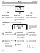
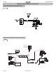


Table Of Contents

Operating Manual
English
www.jacuzzi.com Page 7
CONTROL PANEL
120VAC
PUMP
PUMP/MOTOR
CONTROL BOX
120V 20A
Decidated GFCI
Circuit Breaker
120V 15A
Decidated GFCI
Circuit Breaker
FOR MODELS
WITH IN-LINE
HEATER
CHROMATHERAPY
LIGHTS
Fig. 9
Whirlpool System Reference Illustrations (Continued)
J4 Control Panel Whirlpool Schematic Diagram
J2 Control Panel Whirlpool with Chromatherapy Schematic Diagram
CONTROL PANEL
AIR VALVE
ASSEMBLY
CHROMATHERAPY
LIGHTS 2X
LEAD CONNECTIONS
4-WHITE-C
3-BLACK-H
2-N/A
1-GREEN-GRD
VIEW A
LEAD CONNECTIONS
4-WHITE-C
3-BLACK-H
2-RED-L
1-GREEN-GRD
VIEW B
CONTROL BOX
120VAC
Pump
Panel
Blower
LED Light
PUMP/MOTOR
ILLUMATHERAPY
LIGHTS 4X
OR
120VAC 15A
Dedicated GFCI
Circuit Required
120VAC 20A
Dedicated GFCI
Circuit Required
SEE VIEW B
SEE VIEW A
OR
PUMP/MOTOR
Air Valve
FOR MODELS
WITH IN-LINE
HEATER
Fig. 8