BUILDER/COMFORT BATH SERIES INSTALLATION AND OPERATING INSTRUCTIONS SERIE DE TINAS BUILDER/COMFORT MANUAL DE INSTALACIÓN Y OPERACIÓN Installer: Leave this manual for homeowner. Homeowner: Read this manual and keep for future reference. Instalador: Deje este manual para el propietario. Propietario: Lea este manual y guardelo para referencia en el futuro.
ENGLISH IMPORTANT SAFETY INSTRUCTIONS READ AND FOLLOW ALL INSTRUCTIONS SAVE THESE INSTRUCTIONS CAUTION: TEST THE GROUND FAULT CIRCUIT INTERRUPTER PROTECTING THIS APPLIANCE PERIODICALLY IN ACCORDANCE WITH MANUFACTURER'S INSTRUCTIONS. WARNING: RISK OF ACCIDENTAL INJURY OR DROWNING; CHILDREN SHOULD NOT USE HYDROMASSAGE BATHTUB WITHOUT ADULT SUPERVISION.
Note: This is a professional grade product. A knowledge of construction techniques, plumbing and electrical installation according to codes are required for proper installation and user satisfaction. We recommend that a licensed contractor perform the installation of all Jacuzzi Whirlpool Bath products. Our warranty does not cover improper installation related problems. ENGLISH PRECAUTIONS • Do not operate the whirlpool system unless the bath is filled with water to at least 1" above the highest jet.
ENGLISH CONTENTS Specifications _________________________________________________________________________ 1-5 Roughing-in Reference _________________________________________________________________ 6-11 Installation Instructions __________________________________________________________________ 12-18 Framing and Support _________________________________________________________________ 12 Skirts ______________________________________________________________________________ 13 Service Access ________________
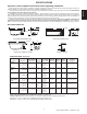
SPECIFICATIONS Important: Read complete instructions before beginning installation. Each whirlpool bath arrives ready for installation, completely equipped with motor/pump assembly and plumbing and fittings necessary for whirlpool operation. An optional drain/overflow kit is available for installation on the bath. Immediately upon receipt, inspect the shell before installing. Should inspection reveal any damage or defect in the finish, do not install the bath.
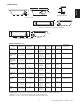
SPECIFICATIONS (Rectangular) ENGLISH MODEL DIMENSIONS DRAIN/OVERFLOW DIMENSIONS TOTAL WEIGHT/ OPERATING PRODUCT CUTOUT FLOOR LOADING GALLONAGE WEIGHT Yes (S750000 HEATER KIT) 80 lb (36kg) Optional, U-Frame Yes (S750000 HEATER KIT) 42 U.S. gal (159 liters) 100 lb (45 kg) Integral Yes (S750000 HEATER KIT) 823 lb (374 kg)/ 53 lb/sq. ft. (259 kg/sq. m) 58 U.S. gal (220 liters) 90 lb (41 kg) Optional, U-Frame NA 662 lb 301 kg)/ 53 lb/sq. ft. (259 kg/sq. m) 38 U.S.
SPECIFICATIONS (Rectangular) MODEL DIMENSIONS SKIRT & MOUNTING HEATER READY FOR FIELD INSTALLATION 97 lb (44 kg) Not Available Yes (S750000 HEATER KIT) 112 lb (51 kg) Integral No TOTAL WEIGHT/ OPERATING PRODUCT CUTOUT FLOOR LOADING GALLONAGE WEIGHT 60" (1524 mm) L* 42" (1067 mm) W 18-1/2" ( 470 mm) H 14-3/4" (375 mm) A 8-1/2" (216 mm) B NA 722 lb (328 kg)/ 41 lb/sq. ft. (200 kg/sq.
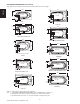
RIMLESS OVAL BATHS W ENGLISH L L 2'' (51 mm) 7-1/2" (191 mm) H 3-1/2" (89 mm) 2" (51 mm) 8" (203 mm) MILANO FRESCO L L W W 2" (51 mm) 2'' (51 mm) H SIDE VIEW END VIEW SIDE VIEW H END VIEW SIDE VIEW END VIEW SIDE VIEW W H END VIEW LUNA RIVA 5 & RIVA 6 GALLERY 5 OVAL & GALLERY 6 OVAL A B SPECIFICATIONS (Oval) DIMENSIONS MODEL FRESCO© DRAIN/OVERFLOW 71-1/2" (1816 mm) L 42" (1067 mm) W 26-1/4" ( 603 mm) H* DRAIN/OVERFLOW DIMENSIONS 20-1/8" (511 mm) A 11-3/4" (299 mm) B CUTOU
CORNER BATHS L A B DRAIN/OVERFLOW END VIEW SIDE VIEW CORNER SIDE BATH 1" H (25 mm) FRONT VIEW SIDE VIEW CAPELLA 55, CAPELLA 60, & TARA WITH INTEGRAL SKIRT 1" (25 mm) H FRONT VIEW SIDE VIEW CAPELLA SPACESAVER WITH INTEGRAL SKIRT SPECIFICATIONS (Corner) MODEL DIMENSIONS DRAIN/OVERFLOW DIMENSIONS CUTOUT TOTAL WEIGHT/ OPERATING PRODUCT FLOOR LOADING GALLONAGE WEIGHT SKIRT & MOUNTING HEATER READY FOR FIELD INSTALLATION CAPELLA© 55 55" (1397 mm) L 55" (1397 mm) L 20-1/4" ( 514 mm) H 17-1/2"
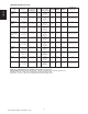
ROUGHING-IN REFERENCE (RECTANGULAR) Note: Baths shown are left-hand unless otherwise specified. Right-hand is a mirror image. 60" ENGLISH *72'' 18'' 16'' x 4'' 12" x 4" 36'' 36" 18" 2'' 14'' AMIGA 9" *72'' CETRA 536 17-3/8'' *60" 16'' x 4'' 36'' 17-3/8" 12" x 4" 2'' 36" 14-1/2'' AMIGA WITH INTEGRAL SKIRT 9" * 72" CETRA 536 WITH INTEGRAL SKIRT 24" *60" 13-1/2" x 4" 8-1/4" 48" 16" 15" x 5" 8-1/2" 13-3/4" (Left-hand only as shown.
ROUGHING-IN REFERENCE (RECTANGULAR) Note: Baths shown are left-hand unless otherwise specified. Right-hand is a mirror image. *60" *72" 9-1/8" 15" x 5" 10" x 4" 30" 42" 2" 2-1/2" 11-7/8" LUXURA 530 WITH INTEGRAL SKIRT 8-3/4" 2" 36" (Right hand shown. Left hand is a mirror image.
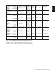
ROUGHING-IN REFERENCE (RECTANGULAR) Note: Baths shown are left-hand unless otherwise specified. Right-hand is a mirror image. *60" ENGLISH *60" 18" 16" x 5" 42" 10" x 4" 36" 12-3/4" 4-1/4" 30" (Right hand only as shown.) SIGNA 5 WITH INTEGRAL SKIRT Front Right Motor/Pump 6-3/4" 2" 9" NOVA 536 *60" *60" 17-1/4" 10" x 4" 36" 42" 13" x 5" 12" 2" 4-1/4" 9-3/4" NOVA 536 WITH INTEGRAL SKIRT 30" 5" (Right hand shown. Left hand is a mirror image.
ROUGHING-IN REFERENCE (OVAL) Note: Baths shown are left-hand unless otherwise specified. Right-hand is a mirror image. These units have been provided with cutout templates included in shipping carton. See CUTOUT information for each model on page 4. ENGLISH 62" 21-1/2" 12" x 4" 43" 43" 12" x 4" 2" 2" 11-3/4" 9-1/2" 36" 71-1/2" (Right hand shown. Left hand is a mirror image.
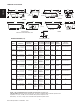
ROUGHING-IN REFERENCE (CORNER) Note: Baths shown are left-hand unless otherwise specified. Right-hand is a mirror image. 55" 33-13/16" 55" 57-1/4" Ref. 55" 12" x 4" 60" 60" 60-1/4" Ref. 16" X 4" 39 1/2" 26" 26" 25-1/4" 32-1/2" 29-3/8" 44 1/2" 9-7/8" 40-7/16" - Junction Box - 2" x 4" Stud (Right-hand only as shown.) 4" 27" 36 1/2" -1 / 27" 36 1/2" 14" X 4" 6" TILE FLANGE 43-7/8" 33-13/16" 41-9/16" 49" - Junction Box (Right-hand only as shown.) (Capella right hand shown.
CUTOUT- CORNER BATHS 53" (1346 mm) 53" 59" (1346 mm) 1499 mm 58" (1473 mm) 59" Ref. 25-1/2" (648 mm) 25-1/2" (648 mm) 25-3/4" (654 mm) 25-3/4" (654 mm) 2-3/4" (70 mm) ENGLISH 58" (1473 mm) 45-9/16" (1157 mm) CAPELLA 60 CAPELLA 60 W/ FRONT LEFT MOTOR/PUMP (Motor/Pump position not shown.) R = 70" CAPELLA 55 3" RADIUS CORNERS (5 PLACES) 57-5/8" Ref. 58" (1473 mm) 58" (1473 mm) 58" (1473 mm) 57" Ref.
ENGLISH Framing and Support The drain/overflow of the bath extends below the bottom of the bath. Note that this requires a cutout in the floor. The floor structure beneath the bath must be able to support a total weight of bath, water, and bather. Refer to the table under total weight for your model. The unit must be supported from the bottom of the bath and not from the bath rim or tile flange. If the subfloor is level and a continuous surface, no other preparation is necessary.
Skirts Corner Baths with Skirt INTEGRAL SKIRT MOUNTING DETAIL CAULKING BEAD SUPPORT FOR CORNER BATHS APPLY ADHESIVE SKIRT PANEL H 2" x 4" STUD U FRAME SKIRT MOUNTING DETAIL FINISHING MATERIALS SECURE SHELL CLIP UNDER CENTER BATH RIM FILLER (Optional) CAULKING BEAD SKIRT PANEL SKIRT FRAME SECURE BOTTOM OF FRAME TO FLOOR Reinstalling Removable Skirt Panel Hold at an angle to the skirt and insert clip under edge of skirt opening. Bow the panel outward and insert clip on other side.
ENGLISH Service Access Service Access with Integral Skirt For partially or fully sunken installations, allow for access to service connections. It is the installer's responsibility to provide sufficient service access. The recommended minimum dimensions allowable for service to the bath are shown in the "Service Access" illustration. Provide adequate area around unit for air circulation for cooling the motor and to supply sufficient air to the jets. Do not insulate this area or around motor.
Electrical Connections ELECTRICAL CONNECTION (FOR CORNER BATHS) 3 PRONG PLUG DUPLEX RECEPT.* 4" MIN. OR IN ACCORDANCE WITH LOCAL BUILDING OR ELECTRICAL CODES DANGER: RISK OF ELECTRIC SHOCK. Connect only to a circuit protected by a Ground Fault Circuit Interrupter. CAUTION: Operating the motor/pump without enough water in the bath can cause leaking and permanent damage to the pump. Before power is applied to the installation, make sure the switch is in the OFF position to avoid pump damage.
Plumbing and Water Supply ENGLISH Drain Information A drain/overflow assembly (sold separately) must be installed on the bath, water tested, and connected to the sanitary system of the house. After opening the carton, inspect for damage and verify that the kit is of the proper finish. In the Jacuzzi Whirlpool Bath drain/overflow kit, note that the waste flange, strainer, overflow cover and cover screws are packaged in a separate package within the kit to protect the trim finish.
UNDERMOUNT INSTALLATION INSTRUCTIONS Installation COUNTER A typical installation will have these construction characteristics. Unit Protection If protective film has been removed, reapply film. For added protection, place a drop cloth or other material in the bottom of bath for protection. Be careful not to scratch the bath surface.
UNDERMOUNT INSTALLATION INSTRUCTIONS ENGLISH COUNTER Position the counter on top of the bath to ensure correct fit and appearance. Make any adjustments that may be necessary. Remove the counter. BATH Adhering Counter to Bath APPLY SILICONE SEALANT TO TOP OF BATH RIM Clean any dirt or debris from the bath rim. Do not use abrasive cleaners. Where the counter will make contact with top of the bath rim, apply a bead of silicone sealant.
OPERATING INSTRUCTIONS Magic Touch® Whirlpool Switch Note: These instructions pertain to all bath products manufactured by Jacuzzi Whirlpool Bath. Not all features discussed in this instruction pamphlet apply to all baths. All baths manufactured by Jacuzzi Whirlpool Bath are designed for "fill and drain," which means the bath should be drained after each use and filled with fresh water by the next bather.
ENGLISH Controlling Whirlpool Action JETS The whirlpool action in your bath is influenced by three factors – direction of flow, force of water, and force of air. All whirlpool baths manufactured by Jacuzzi Whirlpool Bath are equipped with adjustable PowerPro® jets, that may be adjustable for one or more of the three factors. DIRECTIONALLY ADJUSTABLE FULLY ADJUSTABLE Direction: To change the direction of the water flow, swivel the jet nozzle to the desired angle.
MAINTENANCE INSTRUCTIONS Suction Cover/Strainer Maintenance To clean your bath, simply use a mild, nonabrasive liquid detergent solution. You can protect and restore the gloss to a dulled acrylic surface by applying an acrylic polish or automotive paste wax. Never use abrasive household cleaners on any Jacuzzi Whirlpool Bath product. Clean the suction cover/strainer of hair and debris when necessary. To do this, remove the center screw and detach the square cover.
General Whirlpool Bath Troubleshooting Guide ENGLISH PROBLEM PROBABLE CAUSES REMEDY No power to pump/motor. Reset GFCI. Pump/motor not plugged in. Insert plug fully into outlet. Magic Touch switch - air tube not connected to switch or to air switch on pump/motor. Reconnect tube to Magic Touch switch or to air switch pump/motor. Pump/motor faulty. Replace pump/motor assembly. Jets are closed. Open jets by rotating counterclockwise. Suction cover may be clogged.
REPAIR PARTS (When ordering parts substitute a color code for the XXX.
REPAIR PARTS ENGLISH (When ordering parts substitute a color code for the XXX.) 1 POSITION AIR CONTROL SUCTION ASSEMBLY SCREW #10-24/2 3959000 KNOB 8267XXX SUCTION COVER/GASKET ASSEMBLY 6651XXX GRAPHIC RING AIR 8263000 SUCTION FITTING 1958000 PANEL.
REPAIR PARTS (When ordering parts substitute a color code for the XXX.
REPAIR PARTS (When ordering parts substitute a color code for the XXX.
REPAIR PARTS (When ordering parts substitute a color code for the XXX.) UNION REPAIR KIT 9250000: O-RING 9231000 ADAPTOR UNION 9234000 MOTOR/PUMP ASSEMBLY WITHOUT BRACKET 7.0A, 115V, 60HZ Y660000. NUT UNION 9233000 7.0A MOTOR/PUMP BRACKET Y463000. 27 Jacuzzi Whirlpool Bath© K272000AC 12/04 ENGLISH MOTOR/PUMP ASSEMBLY WITH BRACKET 10A, 115V, 60HZ H412000 or 7.
ENGLISH RAPIDHEAT REPAIR PARTS RAPIDHEAT REPAIR HEATER DISCHARGE SIDE U394000 UNION GASKETS (2) Y671000 TAILPIECE (2) Y670000 RAPIDHEAT REPAIR HEATER SUCTION SIDE S749000 UNION GASKETS (2) G947000 TAILPIECE (2) T180000 NOTE: Suction RapidHeat heater components and Discharge RapidHeat heater components are not interchangable.
ENGLISH PRODUCT SPECIFICATIONS ARE SUBJECT TO CHANGE WITHOUT NOTICE. USE INSTALLATION INSTRUCTIONS SUPPLIED WITH PRODUCT. Jacuzzi Whirlpool Bath has obtained applicable code (standards) listings generally available on a national basis for products of this type. It is the responsibility of the installer/owner to determine specific local code compliance prior to installation of the product.
ENGLISH Authorized Service If you need a referral for a service company near you, or need assistance with operation or maintenance related questions, please call our Service Support Department at 1-800-288-4002. For service agent listing, visit our web site at http://www.jacuzzi.com/. To find the service agent listings, click on “For The Trade”. Then click on Electrical/ Mechanical Service Agents.
Jacuzzi Whirlpool Bath Limited Warranty Builder Group Bath Product WARRANTY COVERAGE Jacuzzi Whirlpool Bath (the “Company”) offers the following express limited warranty to the original purchaser of any Jacuzzi Whirlpool Bath Builder Group Bath Product (“unit”) who purchases the product for personal or single family use (“user”). The Company will repair or replace, at its option, the unit or its equipment in accordance with the following terms and conditions.
RESPONSIBILITIES OF OTHERS Inspecting the unit prior to installation is the responsibility of the installer or building contractor who acts on behalf of the user. They are responsible for ensuring the unit is free of defect or damage. Notices are placed on and in the unit and on the shipping carton advising the installer of this responsibility. In the event of a problem, the unit must not be installed.
MANUAL DE INSTALACIÓN Y OPERACIÓN Instalador: Deje este manual para el propietario. Propietario: Lea este manual y guardelo para referencia en el futuro.
INSTRUCCIONES IMPORTANTES SEQURIDAD LÉA Y SIQUE TODAS LAS INSTRUCCIONES GUARDE ESTAS INSTRUCCIONES CAUTELA: EXAMINE EL INTERRUPTOR CON CIRCUITO DE TIERRA QUE PROTÉGE ESTE APARATO PERIÓDICAMENTE, DE ACUERDO A LAS INSTRUCCIONES DE FABRICACIÓN. ESPAÑOL ADVERTENCIA: RIESGO DE LESIONARSE O AHOGARSE ACCIDENTALMENTE; LOS NIÑOS NO DEBERÍAN USAR LA BAÑADERERA DE HIDROMASAJE SIN LA SUPERVISIÓN DE UN ADULTO. ADVERTENCIA: PARA EVITAR LESIONARSE, OBRE CON PRUDENCIA CUANDO ENTRA O SALE DE LA BAÑADERA DE HIDROMASAJE.
Nota: Este es un producto de calidad profesional. Para una instalación apropiada y la satisfacción del usuario, se requiere de un conocimiento de acuerdo a los códigos en las técnicas de construcción, plomería y eléctricidad. Recomendamos que un contratista licenciado efectúe la instalación de todos los productos de Jacuzzi Whirlpool Bath. Nuestra garantía no cubre los problemas que resulten de una instalación inadecuada.
TABLA DE CONTENIDO Especificaciones ______________________________________________________________________ 1-5 Diagramas de instalaciones ______________________________________________________________ 6-11 Instrucciones de instalación ______________________________________________________________ 12-18 Estructura y soporte __________________________________________________________________ 12 ESPAÑOL Faldón _____________________________________________________________________________ 13 Registros _________
ESPECIFICACIONES Importante: Lea las instrucciones antes de iniciar la instalación. Las tinas de hidromasaje se entregan listas para instalarse y completamente equipadas con motor, bomba, accesorios de plomería y mecanismos necesarios para el hidromasaje. La instalación del equipo de desagüe y rebosadero es opcionál. Saque la tina de su caja; consérvela hasta haber revisado completamente el producto. No levante la tina sujetándola por los accesorios de plomería, sino por el casco.
ESPECIFICACIONES ESPAÑOL MODELO (Rectangular) MEDIDAS DEL DESAGÜE/ REBOSADERO CARGA TOTAL SOBRE EL PISO FALDÓN Y MONTAJE CALENTADOR LISTO PARA LA INSTALACIÓN DEL CAMPO CAPACIDAD PESO 60" (1524 mm) L* 36" ( 914 mm) W 21-1/4" ( 553 mm) H 18-1/2" ( 470 mm) A 9" ( 229 mm) B NA 742 lb (337 kg)/ 50 lb/sq. ft. 244 kg/sq. m 48 U.S.
ESPECIFICACIONES MODELO (Rectangular) MEDIDAS MEDIDAS DEL DESAGÜE/ REBOSADERO CORTE CARGA TOTAL SOBRE EL PISO CAPACIDAD PESO FALDÓN Y MONTAJE CALENTADOR LISTO PARA LA INSTALACIÓN DEL CAMPO NOVA 5 CON PESTAÑA DE 3 LADOS INTEGRADA 60" (1524 mm) L* 42" (1067 mm) W 18-1/2" ( 470 mm) H 14-3/4" (375 mm) A 8-1/2" (216 mm) B NA 722 lb (328 kg)/ 41 lb/sq. ft. (200 kg/sq. m) 45 U.S.
TINAS OVALADAS SIN BORDES W L L 2'' (51 mm) 7-1/2" (191 mm) H 3-1/2" (89 mm) 2" (51 mm) 8" (203 mm) VISTA DE FRENTE VISTA LATERAL W VISTA DE FRENTE VISTA LATERAL FRESCO MILANO L L W ESPAÑOL H W 2" (51 mm) 2'' (51 mm) H VISTA LATERAL VISTA DE FRENTE VISTA LATERAL H VISTA DE FRENTE LUNA A RIVA 5, RIVA 6 GALLERY 5, GALLERY 6 B ESPECIFICACIONES MODELO DESAGÜE/REBOSADERO (Ovaladas) MEDIDAS MEDIDAS DEL DESAGÜE/ REBOSADERO CORTE 20-1/8" (511 mm) A 11-3/4" (299 mm) B Plantilla
TINAS DE ESQUINA L A 2" (51 mm) H B DESAGÜE/REBOSADERO VISTA DE FRENTE VISTA LATERAL ACAPARE el BAÑO del LADO 1" (25 mm) H VISTA DE FRENTE VISTA LATERAL ESPAÑOL CAPELLA 55, CAPELLA 60, & TARA CON FALDÓN INTEGRADO 1" (25 mm) H VISTA DE FRENTE VISTA LATERAL CAPELLA SPACESAVER CON FALDÓN INTEGRADO ESPECIFICACIONES MODELO (De Esquina) MEDIDAS MEDIDAS DEL DESAGÜE/ REBOSADERO CORTE CARGA TOTAL SOBRE EL PISO CAPACIDAD PESO FALDÓN Y MONTAJE CALENTADOR LISTO PARA LA INSTALACIÓN DEL CAMPO
DIAGRAMAS EN PLANTA DE INSTALACIONES (RECTANGULAR) Nota: Las instalaciones de estas tinas van del lado izquierdo a menos que se especifique lo contrario. En las tinas derechas van del lado contrario.
DIAGRAMAS EN PLANTA DE INSTALACIONES (RECTANGULAR) Nota: Las instalaciones de estas tinas van del lado izquierdo a menos que se especifique lo contrario. En las tinas derechas van del lado contrario. *60" *72" 9-1/8" 14-1/2" 10" x 4" 15" x 5" 30" 42" 2" 11-7/8" 2-1/2" 36" LUXURA 530 CON FALDÓN INTEGRADO *60" (Mano derecha mostrado. La mano zuierda es una imagen del espejo.
DIAGRAMAS EN PLANTA DE INSTALACIONES (RECTANGULAR) Nota: Las instalaciones de estas tinas van del lado izquierdo a menos que se especifique lo contrario. En las tinas derechas van del lado contrario. *60" *60" 18" 10" x 4" 16" x 5" 42" 36" 12-3/4" 2" ESPAÑOL 9" 6-3/4" NOVA 536 4-1/4" 30" (Mano derecha (como mostrado) solamente) 60" SIGNA 5 CON FALDÓN INTEGRADO *60" 18-1/8" 10" x 4" 36" 42" 2" 10-1/8" NOVA 536 CON FALDÓN INTEGRADO 13" x 5" 12" 4-1/4" 30" 5" (Mano derecha mostrado.
DIAGRAMAS EN PLANTA DE INSTALACIONES (OVALADAS) Nota: Las instalaciones de estas tinas van del lado izquierdo a menos que se especifique lo contrario. En las tinas derechas van del lado contrario. Estas unidades se han proporcionado con plantillas de recorte incluidas en el envío el cartón. Vea información de RECORTE para cada modelo en la página 4. 62" 12" x 4" 43" 21-1/2" 2" 43" 12" x 4" 2" 36" 11-3/4" 9-1/2" 71-1/2" (Mano derecha mostrado. La mano zuierda es una imagen del espejo.
DIAGRAMAS EN PLANTA DE INSTALACIONES (ESQUINA) Nota: Las instalaciones de estas tinas van del lado izquierdo a menos que se especifique lo contrario. En las tinas derechas van del lado contrario. 33-13/16" 32-1/4" 55" 55" 55" 57-1/4" Ref.
DIAGRAMA EN PLANTA DE TINAS DE ESQUINA 53" (1346 mm) 53" (1346 mm) 58" (1473 mm) 59" 1499 mm 58" (1473 mm) 59" Ref. 25-1/2" (648 mm) 25-1/2" (648 mm) 25-3/4" (654 mm) 25-3/4" (654 mm) CAPELLA 60 CAPELLA 60 Motor/Bomba Delantero Izquierdo (Posición de motor/Bomba no mostrada.) R = 70" CAPELLA 55 ESPAÑOL 2-3/4" (70 mm) 45-9/16" (1157 mm) 3" RINCÓNES DE RADIO (5 LUGARES) 58" (1473 mm) 57-5/8" Ref. 58" (1473 mm) 57" Ref.
INSTRUCCIONES DE INSTALACÍON ESPAÑOL Estructura y Soporte La instalación del desagüe y el rebosadero se extiende por debajo de la parte inferior de la tina. Cabe señalar que para esto se requiere hacer un corte en el piso. La estructura del piso, debajo de la tina, debe poder soportar el peso total de la tina, el agua, y el ocupante. Referirse al cuadro correspondiente al peso total de su modelo.
FALDÓN Tinas de Esquina con Faldón Si se usa faldón en la tina de esquina, es necesario contar con mayor soporte en la parte frontal de la unidad. Mida la altura del piso a laparte inferior del borde de la tina. Corte dos muros de 2" x 4", aplique el pegazulejos en ambos extremos e instale (Véase el Diagrama de Instalación).
Acceso para Servicio Acceso Faldón Integrado En el caso de instalaciones parcial o totalmente empotradas, deje un acceso a las conexiones. Es responsabilidad del instalador dejar espacio suficiente para el registro. Las medidas mínimas recomendables para el registro de la tina se muestran en la ilustración que lleva el nombre de “Registros”. Provee área adequada al rededor de la tina para circulación de aire para enfriamiento del motor y para proveir aire suficiente a los chorros.
Conexiones Eléctricas CONEXIÓN ELÉCTRICA (PARA TINES DE ESQUINA) Se requiere un circúito independiente protegido con un interruptor de circuito para fallas a tierra (ICFT). Instale un contacto dúplex en el muro debajo de la tina, por lo menos 4 pulgadas arriba del piso. No se incluye el contacto dúplex porque están fabricadas con un seguro y cómodo interruptor ON/OFF Magic Touch.
Plomería y Suministro de Agua Información Sobre el Drenaje Debe instalarse una unidad de drenaje/rebosadero (se vende separado) en la tina, verificar que no presente fugas y conectarse al sistema sanitario de la casa. Después de abrir la caja de cartón, verifique que no hay daños y revise el acabado. En la unidad de drenaje/rebosadero de Jacuzzi Whirlpool Bath, la pestaña, el filtro, la placa protectora de rebose y los tornillos de la placa vienen en un paquete por separado para proteger el terminado.
INSTRUCCIONES de INSTALACION de UNDERMOUNT Instalación MOSTRADOR Una instalación típica tendrá estas características de la construcción. MORTERO* *El MORTERO DEBE ESTAR EN el CONTACTO CON TODOS PIES de ESPUMA Protección de Unidad Si la película protectora se ha quitado, reapply película. Para la protección agregada, coloque una tela de gota u otra materia en el fondo del baño para la protección. Tenga cuidado para no rasguñar la superficie del baño.
INSTRUCCIONES de INSTALACION de UNDERMOUNT MOSTRADOR ESPAÑOL Posicione el mostrador encima del baño para asegurar el ataque y la apariencia correctos. La marca cualquier ajuste que puede ser necesario. Quite el mostrador. BAÑO Que Adhiere Contra al Baño APLIQUE SILICONA SELLADOR para SOBREPASAR DE BORDE de BAÑO Limpie cualquier tierra o los escombros del borde del baño. No utilice la tintorería abrasiva.
INSTRUCCIONES OPERADORAS OPERACIÓN Interruptor Neumático Magic Touch® Nota: Estas instrucciones se aplican a todos los productos para baño fabricados por Jacuzzi Whirlpool Bath. No todas las características descritas en el folleto de instrucciones se aplican a todas las tinas.
CHORROS Cómo Controlar el Sistema Hidroterapeútico El funcionamiento del sistema hidroterapeútico de la tina lo determinan tres factores: dirección del flujo, fuerza del agua y fuerza del aire. Todas las tinas fabricadas por Jacuzzi Whirlpool Bath están equipadas con chorros regulables PowerPro®, que pueden ajustarse con respecto a esos tres factores. Algunas tinas cuentan con chorros regulables sólo en cuanto a dirección y flujo del aire.
INSTRUCCIONES de CONSERVACION Placa Protectora de Succión/Mantenimiento del Filtro Cómo Limpiar la Tina Para limpiar la tina sólo use detergentes líquidos suaves, no abrasivos. Puede proteger y recuperar el brillo de la superficie acrílica aplicando terminados una cera acrílica de igual calidad o cera para pulir automóviles. Nunca use limpiadores abrasivos para el hogar en ningún producto Jacuzzi Whirlpool Bath.
Guía General de Reparo de Fallas Baños Hydroterapeúticos PROBLEMA SOLUCIÓN No llega corriente a la bomba/motor. Reconecte el GFCI. No está conectada la bomba/motor. Insertar totalmente el enchufe en el tomacorriente. Interruptor Magic Touch Switch – El tubo de aire no está conectado al interruptor, o al interruptor de aire en la bomba/motor. Reconectar el tubo al interruptor Interruptor Magic Touch Switch o al interruptor de aire de la bomba/motor. Bomba/Motor defectuosa.
PIEZAS DE REPUESTOS (Al ordenar las partes substituyen un identificado por colores para el XXX.
PIEZAS DE REPUESTOS (Al ordenar las partes substituyen un identificado por colores para el XXX.
PIEZAS DE REPUESTOS (Al ordenar las partes substituyen un identificado por colores para el XXX.
PIEZAS DE REPUESTOS (Al ordenar las partes substituyen un identificado por colores para el XXX.
PIEZAS DE REPUESTOS (Al ordenar las partes substituyen un identificado por colores para el XXX. ) ASAMBLEA de la MOTRIZ/BOMBA CON PARENTESIS 10A, 115V, 60HZ H412000 or 7.0A, 115V, 60HZ BG94000 JUEGO DE REPARACION DE UNION 9250000: ARO TORICO 9231000 ESPAÑOL ADAPTADOR DE UNION 9234000 ASAMBLEA de la MOTRIZ/BOMBA SIN PARENTESIS 7.0A,115V,60HZ Y660000 TUERCA DE UNION NUT 9233000 7.
ESPAÑOL PIEZAS DE REPUESTOS CALENTADOR DE REPARACION "RAPIDHEAT" LADO de SUCCION S749000 JUNTAS DE CULATA de UNION (2) G947000 ANEXO(2) T180000 CALENTADOR DE REPARACION "RAPIDHEAT" DESCARGUE el LADO U394000 JUNTAS DE CULATA de UNION (2) Y671000 ANEXO(2) Y670000 NOTA: los componentes de calentadora de Succión RapidHeat y componentes de calentadora de Descarga RapidHeat no son interchangable.
ESPAÑOL LAS ESPECIFICACIONES DEL PRODUCTO ESTÁN SUJETAS A CAMBIOS SIN PREVIA NOTIFICACIÓN USE LAS INSTRUCCIONES DE INSTALACIÓN PORPORCIONADAS CON EL PRODUCTO. Jacuzzi Whirlpool Bath ha obtenido las listas de códigos correspondientes (standards), para productos de este tipo, que generalmente están a disposición por todo el país. Antes de instalar el producto, el instalador o dueño de éste tiene la obligación de cumplir con el código específico local.
Servicios Autorizados Productos para el Baño y la Ducha ESPAÑOL Si usted necesita obtener referencias sobre una compañía de servicios en su cercanía, o necesita asistencia para preguntas sobre la operación o mantenimiento del producto, por favor llame a nuestro Departamento de Servicios de Apoyo, teléfono 1-800-288-4002. Para obtener una lista de agentes de servicios, visite nuestro sitio en el web, http://www.jacuzzi.com/. Para encontrar listas de agentes de servicios, de un clic en “For The Trade”.
Garantía Limitada de Tinas de "Jacuzzi Whirlpool Bath" Producto de Grupo de Tinas Builder COBERTURA DE LA GARANTÍA Jacuzzi Whirlpool Bath ( la "Compañía") ofrece la siguiente garantía limitada expresa a los compradores originales de cualquier tina de Jacuzzi Whirlpool Bath Builder Group Bath Product ("unidad") que compren el producto para uso personal o de una sola familia ("usuario").
RESPONSABILIDAD DE TERCEROS Es responsabilidad del instalador o del contratista constructor que actúen en nombre del usuario realizar una inspección de la unidad antes de instalarla. Ellos son responsables de asegurarse de que la unidad no tiene defectos ni daños. Se ponen avisos en la unidad y en la caja que la contiene para advertir al instalador sobre esta responsabilidad. En caso de que haya algún problema, no debe instalarse la unidad.