
Installation Guide

English
Freestanding Baths
Installation Instructions www.jacuzzi.com Page 5
Installation Instructions for 1-Piece Tub
1
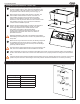
Set the tub in its place and position precisely with respect to
the drain-overow location. Verify where the indentation for the
drain is in relation to the drain-overow. Use a marker to outline
the perimeter of the entire tub directly on the oor (Fig. 2).
2
Mark a trough for the overow drain location on the oor. The
drain/overow extends below the bottom of the bath. The
drain/overow requires a cutout of the oor for providing
space to accommodate the extension. Do not exceed the
dimensions of the tub perimeter. When the above locations have
been marked on the oor, remove the tub, set it aside and
continue with the installation process.
3
Prepare the drain/overow trough according to the dimensions
shown in the Technical Specications section. The depth
of the trough depends on the vertical extension of the
drain elbow at the bottom of the plumbing below
the oor level. Install the drain/overow according to the
manufacturer’s instructions. Refer also to the Technical
Specications section.
Watertight installation of the drain is the installer’s responsibility.
Drain leakage is excluded from the Jacuzzi Luxury Bath warranty of
this product.
4
Before the tub may be secured to the oor, the following steps must
be completed: Place the tub on the oor in relation to the drain/
overow. Place the tub on the oor and line up with the markings
previously made on the oor.
Floor-mounted or wall-mounted faucetry can be used exterior to the
bath, this can be installed after the bath is installed into the oor.
Clean up debris left over from the construction steps taken thus far. Also, remove the perimeter outline of the template on
5
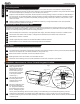
the oor. Use silicone to attach tub to the sub oor. Make sure the tub is properly oriented according to the drain/overow
end.
A bead of silicone sealant should be applied around the bottom of the tub. Carefully place the tub on the oor in the correct
position and press to the oor. Place weights around the perimeter and allow the adhesive to cure before proceeding.
Side View
Silicone
Bottom View
Fig. 2
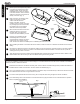
Overow Drain Hole Cutouts
Cutout (Fig. 3) Drain Part Number
Linear Drain MF35XXX
Rotary Drain HP55XXX
Avvio Collection Integral
Deep Soak Drain LH33XXX
Slip Cover Drain PG35XXX
Fig. 3
0.63”
(16mm)
0.38”
(9.65mm)
0 2.5”
(63.5mm)
3.5”
(88.9mm)
MF35
HP55
PG35
SOLID
SURFACE
LH33
3.13”
(79.5mm)