
Installation Guide

4
Installation Instructions Instrucciones de Instalación
This faucet complies with NSF61/9, ASME/ANSI A112.18.1
and CSA B 125 Standards.
Este grifo se encuentra conforme con losestandares de NSF61/9,
de ASME/ANSI A112.18.1 y de CSA B 125.
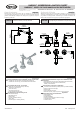
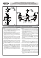
See figs. 1, 3.1-3.4
1.
2.
Veá dis. 1, 3.1-3.4
1.
2.
3.
1
INSTALLATION OF VALVES AND LEVERS
MONTAJE DE VÁLVULAS Y PALANCAS
3.1 3.2 3.3 3.4
MAX. 1-3/16"
(MAX. 30mm)
ENGLISH
~
Check the marker on the valve (see 'Set-up Diagram') to identify the
hot water (red marker) and cold water (blue marker) valves. (fig 2)
Feed the valve (9K) along with the previously attached flange nut
(26), metal washer (27) and rubber washer (28) through the
installation opening in the sink. (fig 3.1, 3.2)
Place the rubber washer (28), metal washer (27) onto the valve
from above and screw on the second flange nut (26), but not too
tightly. (fig 3.2)
ESPANOL
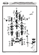
3.
Place the handle base (15) on the mounting surface of lavatory.
Screw on the shroud (14) on the valve (9L), then place the handle
(12,13) on the splines of the valve head, check that the distance 'H'
left (fig. 3.2) is sufficient to allow elements (14) and (12,13) to fit
properly if not, remove elements (15) and (13,14), and adjust the
distance 'H' with the flange nuts (26). (fig. 3.3) After choosing the
appropriate distance 'H', screw home the flange nut (26) (fig 3.3).
Replace the shroud (14) onto the valve (9L) and screw on the shroud
(14) until clear resistance is felt, then place the handle (12,13) in the
appropriate position on the splines of the valve head (9L)(turn the
left handle (item 12, fig. 1) all the way to the left until it is in the OFF
position, the right handle all the way to the right (item 12, fig.1)). After
selecting the appropriate positioning screw home the attaching screw
(16) with the hex key (K1) (included with the faucet). (fig 3.4)
Repeat the above for the second valve and handle.
4.
Compruebe el indicador en la válvula (mire "Diagrama de Instala-
ción”) para identificar la válvula del agua caliente (indicador rojo) y
fría (indicador azul). (dis. 2)
Meta por el agujero de montaje del lavabo la válvula (9L) con la tuerca
de bridas (26) la arandela de metal (27) colocada antes y con la
arandela de goma puesta (28). ( dis. 3.1, 3.2)
Desde arriba ponga una arandela de goma (28) en la válvula (9L) y
desde arriba ponga una arandela de metal (27) y ponga otra tuerca
(26) de bridas, pero no la apriete demasiado. (dis. 3.2)
Ponga base de la volante (15) en la superficie de montaje del
lavabo. Ponga la protección del volante (14) en la válvula (9L),despu-
és ponga la palanca (12,13) en la multicuña de la cabeza de válvula,
compruebe si la distancia „H” (dis. 3.2) es suficiente para garantizar
el encajamiento correcto de los elementos (14) y (12,13) si no
desmonte los elementos (14) y (12,13) corrija la distancia „H” con las
tuercas de bridas (26). (dis. 3.3)
9L
26
28
27
9L
26
27
28
28
27
26
15
14
H=~2-9/16"
(H=~65mm)
4.
5.
6.
5.
6.
ENGLISH
~
ESPANOL
2
SPOUT & CONNECTION INSTALLATION
INSTALACIÓN Y CONECCION DEL GRIFO
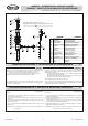
1.
2.
3.
1.
2.
3.
4.
4.
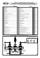
See figs. 4, 5 Veá dis. 4, 5
K1
16
1312
Position the spout base (5) on the bath tub ledge.
Insert shank (19) of the spout (A) through center hole of bath tub
ledge. From underneath the ledge place rubber washer (21) and
metal washer (22) on the shank, then screw on the flanged nut
(23). Make sure that the spout (A) is in the correct position. Hand
tighten only the flanged nut (23).
Thread the T-connection (25) on the shank of the spout as shown
in fig. 4
Loop hose (31) as shown in fig. 5 and screw on the hose nut to the
T-connection inlet. Repeat step for second hose (31).
NOTE: Be sure not to kink the hoses.
Posicionar la base del caño (5) en el saliente de la bañera.
Insertar el tubo enroscado (19) del caño (A) a través del saliente del
agujero central de la bañera. Por debajo del saliente colocar una
arandela de goma (21) una arandela de metal (21) sobre el tubo,
luego apretar la tuerca (23). Controlar si del caño (A) se encuentra
en la posición apropiada el saliente de la bañera. Apretar la tuerca
(23) únicamente a mano.
Colocar la conexión T (25) sobre el tubo del
caño como lo
presenta la dis. 4.
Colocar la manguera (31) como lo presenta la fig. 5 y apretarla con
la tuerca de la manguera a la entrada de la conexión T. Repita
el paso
para el segundo manguera (31).
NOTA: Asegurarse de no plegar las mangueras.
Después de elegir la distancia „H”
adecuada, apriete la superior tuerca de bridas (26).
De nuevo ponga la protección de volante (14) en la válvula (9L) y
pong la protección de volante (14) hasta el momento de sentir una
resistencia notable, después ponga la palanca (12,13) en la
multicuña de la cabeza de válvula (9L) en la posición adecuada (dé
una vuelta a la palanca izquierda máximamente a la izquierda, así que
la válvula quede en la posición (posición 12, dis. 1) máximamente a
la izquierda, así que la válvula quede en la posición „CERRADA”, en
caso de la palanca derecha (posición 12, dis. 1) máximamente a la
derecha). Después de elegir la colocación correcta apriete bien el
tornillo sujetador (16) con la llave en forma de la letra “L” con el corte
hexagonal (K1) (adjuntado a la batería) (dis. 3.4).
Todas las actividades mencionadas repita para otra válvula y otro
volante.
Insert nozzle (25) and seal o-ring (24) into T-connection (20).
Inserte el inyector (25) y la empaquetadura de anillo (24) en la
conección „t” (20).
BARREA™ WIDESPREAD LAVATORY FAUCET
BARREA™ GRIFO DE DOS MANILLAS DE EXTENSIÓN
IOG 2889.00
Rev. 1 January 2017