
Installation Guide

5
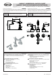
Installation Instructions Instrucciones de Instalación
This faucet complies with NSF61/9, ASME/ANSI A112.18.1
and CSA B 125 Standards.
Este grifo se encuentra conforme con losestandares de NSF61/9,
de ASME/ANSI A112.18.1 y de CSA B 125.
5
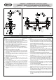
4
A
5
20
31
31
9R
9L
19
21
22
20
23
24
25
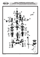
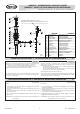
See fig. 6
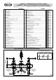
Dismantle the drain assembly to the parts shown on fig. 6.
Insert collar gasket (4) and drain collar (3) into drain hole of a
lavatory. From underneath the lavatory slip under-bowl gasket (5)
into drain collar (3), washer (6) and flanged nut (7).
Position under-bowl gasket (5) correctly under the lavatory and
screw flanged nut (7) firmly but do not overtighten.
Make sure washer (8) is inside drain body (9) and screw drain body
(9) onto drain collar (3) hand tighten only.
Pay attention to align the drain body (9) so that the horizontal hole
of drain body will be in the same plane as a lift rod ( 30, fig.1).
Tighten drain body (9) onto drain collar (3) and tighten the flanged
nut (7).
1.
2.
3.
4.
5.
Veá dis. 6
Desmontar las piezas del drenaje según lo demostrado en la dis. 6.
Inserte la empaquetadura superior (4) y el tapon del drenaje (3) en
el agujero del drenaje de un servicio. Colaque por debajo del
lavatorio la empaquetadura inferior (5) en el collar del drenaje (3),
la arandela (6) y tuerca de montaje (7).
Coloque la empaquetadura inferior (5) correctamente debajo del
servicio y entornille a tuerca de montaje (7) firmemente pero no
apriete demasiado.
Cerciorese de que la arandela de tubo (8) este en el cuerpo del
drenaje (9) y entornille el cuerpo del drenaje (9) en el collar del
drenaje (3) apriete solamente con la mano.
Preste atención en alinear el cuerpo del drenaje (9) de modo que el
agujero horizontal del cuerpo del drenaje esté en el mismo plano
que la varilla elevadora ( dis. 1, elem. 30 ). Apriete el cuerpo
del drenaje (9) sobre el collar del drenaje (3) y apriete la tuerca de
montaje (7).
ENGLISH
~
ESPANOL
1.
2.
3.
4.
5.
DRAIN ASSEMBLY INSTALLATION INSTALACIÓN DEL DRENAJE
3
6.
7.
8.
9.
10.
6.
7.
8.
9.
10.
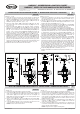
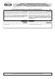
Insert drain plug (2) into drain collar (3).
Remove clip (15) from ball rod (12); undo a ball rod nut (13)
from body, take out sealing washer (11) from a nut and push the
nut forward over ball rod (12) from the longer end with the thread
facing a ball.
Insert the sealing washer (11) and the ball rod (12) into a side hole
of drain body (9). Make sure that the rod ending goes under the
plug screw head.
Tighten ball rod nut (13) making sure that the ball rod seat (11)
and ball joint are properly installed.
®
Add Teflon tape to tail tube (10), and mount tail tube to drain
body (9).
Lift the drain plug (2) to an open position, by lowering the horizontal
ball rod (12) down.
Insert lift rod (30, fig.1) down through faucet base (3, fig.1)
and top of lift rod strap (14). Adjust to proper height and tighten
screw (16).
Choose the position of horizontal ball rod (12) in one of the holes in
lift rod strap (14). Insert horizontal ball rod (12) through one arm
of spring clip (15) and lift rod strap (14) and then second arm of
spring clip (15).
Try if a drain plug (2) closes the drain by pulling the lift rod. If not,
make corrections of position of lift rod strap (14) and horizontal ball
rod (12).
11.
12.
13.
14.
Inserte el tapón de drenaje (2) en el collar del drenaje (3).
Quite el clip de la abrazadera de muelle
(15) de varilla de bola (12);
retire la tuerca de varilla de bola (13) del cuerpo, tome hacia fuera
el arandela selladora (11) a lo largo de varilla de bola (12) del
extremo más.
Inserte el arandela selladora (11) y el varilla de bola (12) en un
agujero lateral del cuerpo del drenaje (9). Asegúrese de que el
extremo de la barra va debajo de la cabeza del tornillo del tapón.
Ajuste la tuerca de varilla de bola (13) serciorandose de que el
asiento de la barra del pivote (11) yel cuerpo del drenaje este
instalado correctamente.
®
Enrrollar la cinta de Teflon para asegurar el pipa de descarga (10),
monte colillo al cuerpo del drenaje (9).
Levante el tapón de renaje (2) a la posición de abierto, moviendo
el varilla de bola (12) hacia abajo.
Inserte la varilla elevadora (dis. 1, elem. 30) por el agujero
en base del grifo (dis. 1, elem.3) y inserte el plato de
ajustamiento (14). Ajuste a la altura apropiada y apriete el tornillo
(16).
Elija la posición de varilla de bola (12) en uno
de los agujeros del
plato de ajustamiento (14). El varilla de bola (12) a través de la
broche (15) y levante el plato de ajustamiento (14) y despues el
segundo brazo de la broche (15).
Intente cerrar con el tapón de drenaje (2)
tirando de la varilla de
elevación. Si no es posible, haga las correcciones de la posición del
plato de ajustamiento (14) y de la barra horizontal de varilla de
bola (12).
d
11.
12.
13.
14.
BARREA™ WIDESPREAD LAVATORY FAUCET
BARREA™ GRIFO DE DOS MANILLAS DE EXTENSIÓN
IOG 2889.00
1/2 1/2
Rev. 1 January 2017