STEAMPRO TM Steam Generator Installation and Operating Manual o r P m Stea
IMPORTANT SAFETY INFORMATION READ ALL INSTALLATION INSTRUCTIONS Jacuzzi Whirlpool Bath does not recommend prolonged periods of use of the steamer. Prolonged use of the steam system can raise excessively the internal human body temperature and impair the body’s ability to regulate its internal temperature (hyperthermia). Consult your physician about your safety and comfort before using the steam system. Limit your use of steam to 10–15 minutes until you’re certain of your body’s reaction.
Contents Installation of Steam Generator Specifications ______________________________________________________________________________ 1 How to Select Generator Size and Electrical Requirements ___________________________________________ 2 Locating the Steam Generator _________________________________________________________________ 3 Room Construction and Ventilation _____________________________________________________________ 3 Plumbing Instructions and Cautionary Notes on Installation __________________
INSTALLATION Specifications and Sizing of the Steam Generator for the Room Single-Phase Electrical Service Required Generator Power Rating at Voltage Size of Enclosure (cubic feet) STEAMPRO 240/5 S 064000 240 VAC 30 AMP 3 WIRE (#10) 5.0 kW@240 60-110 208 VAC 30 AMP 3 WIRE (#10) 3.75 kW@208 60-80 STEAMPRO 240/7 S 062000 240 VAC 40 AMP 3 WIRE (#8) 7.0 kW@240 110-220 208 VAC 40 AMP 3 WIRE (#8) 5.25 kW@208 80-150 STEAMPRO 240/10 S 060000 240 VAC 60 AMP 3 WIRE (#6) 10.
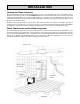
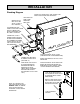
INSTALLATION Locating the Steam Generator The steam generator must be installed upright and level. The steam generator must be located within a 25 foot maximum steam line run to the steam head AND within the 25 foot control wire length to any controls. It may stand attached to a horizontal base or to a wall. For wall mounting, use “keyhole” slots on a cabinet back to slip over screw heads and install a wood cleat or shelf to the wall at the bottom of the unit to help support the bottom.
INSTALLATION Plumbing Instructions and Cautionary Notes on Installation Minerals in the water or poor water quality can shorten the life of the steam generator or cause erratic operation if the tank is not drained regularly. Drain the tank frequently. Jacuzzi Whirlpool Bath also strongly recommends purchasing and installing the optional drain down valve. See the important note below. The tank will be drained automatically after each use after the water temperature lowers.
INSTALLATION Plumbing Diagram STEAM UNIT TO BE LEVEL AND UPRIGHT SEE PAGE 5 FOR SUGGESTED LOCATIONS WATER SUPPLY WITH SHUT-OFF VALVE (3/8 OR 1/2 INCH COPPER) SEE CHART ON PAGE 4 FOR REQUIRED WIRE SIZE. TO STEAM HEAD SEE PAGES 8 AND 9 FOR STEAM HEAD PLUMBING AND INSTALLATION FOR VARIOUS WALL SURFACES. STEAM PIPE 1/2 INCH (MINIMUM SIZE) COPPER. 25 FOOT TOTAL MAXIMUM RUN. DO NOT PLACE ANY VALVES OR DIPS IN THIS LINE.
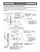
INSTALLATION Steam Head Installation for Various Wall Surfaces Jacuzzi Whirlpool Bath recommends that the steam shield be used for all steam head installations. The steam shield must be installed if the steam head is located on acrylic (or other plastic) wall surfaces or above a bath rim. The steam head is to be installed at 18 inches minimum height above the floor or shower base. The steam head is to be installed at 10 inches minimum above a bath rim.
INSTALLATION 10 kW Steam Generator with Two Steam Heads Two steam heads may be installed with the Model E210000 Steam Generator, if desired. This will reduce the sound level of the exiting steam and will provide more even steam distribution and less heat concentration in larger steam enclosures.
INSTALLATION Automatic Drain Valve Installation (Optional) Important Note About Tank Drain Selection: Jacuzzi Whirlpool Bath strongly recommends purchasing and installing the optional Automatic Drain Valve for the steam generator. This valve prevents standing water from remaining in the tank between uses. This valve must be installed where the steam generator may be exposed to freezing temperatures, e.g., in seasonaluse homes. This valve automatically drains the tank when the water has cooled.
INSTALLATION Steam Controls—Available Installation Methods Various control packages are available for use with the steam generator. The following instructions (A–C, pages 12 - 16) describe the different installations. Select one of the following control options: A. ON/OFF 30 minute control. S061827 S061829 (no sensor, no cable B. 30 minute temperature control. S083827 S083827 C. Digital time and temperature control.
INSTALLATION A. STEAM CONTROL BY 30 MINUTE LOW VOLTAGE ON/OFF CONTROL. 1. Control cable rough-in: The low voltage control can be mounted up to 75 feet from the generator either inside or outside the steam room. (A 25’ cable provided.) Also, see # 4 Optional Secondary Generator Control. String (3) 18 to 22 AWG solid wires from the control location through 1/2" holes in the wall studes or ceiling joists to the generator.
INSTALLATION GENERAL INSTRUCTIONS FOR TEMPERATURE CONTROL MODELS 1. Control Cable Rough-in The low voltage control can be mounted up to 25 feet from the generator either inside or outside the steam room, also see #6 optional secondary digital generator control. String the 25' cable from the control location through 1/2" holes in the wall studs or ceiling joists to the generator. Note: Do not staple through or damage cable. Use factory supplied cables only.
INSTALLATION 5. INSTALL GENERATOR CONTROL The low voltage control can be mounted directly to a finished wall either inside or outside the steam room. TEMPERATURE SENSOR PLUG (J4) Using a 2" hole saw, drill a hole in the finished wall where the control is to be mounted (the control cable should OPTIONAL AUTOMATIC already be roughed-in to this location). Locate the control DRAIN CONNECTION cable, pull it out through the 2" hole and plug it into the SK1 SK3 connector on the back of the control housing.
OPERATION B. 30 MINUTE TEMPERATURE CONTROL The 30 minute temperature control features a 30 minute press on timer lighting up the word "STEAM" and a thermostatic control preset to reach 120 degrees Fahrenheit. The digital control can be mounted either inside or outside the steam room. The preset temperature can be adjusted in a range between 100 degrees and 125 degrees Fahrenheit.
OPERATION C. DIGITAL TIME AND TEMPERATURE CONTROL The digital control features an adjustable 60 minute time and temperature control with digital display. The actual room temperature and time remaining are alternately displayed every 5 seconds. The primary control can be mounted either inside or outside the steam room and an optional secondary control is available to mount in an alternate location.
SERVICE Description of SteamPro Steam Generator The SteamPro series generator is the latest in modern steam generator design. The SteamPro steam generator uses a printed circuit assembly to monitor and control all the equipment needed to produce steam. The system has three functions: a timer that controls the length of the steam bath; the operating water level is monitored and controlled; and the heating elements are protected by a minimum water level sensor.
TROUBLESHOOTING There are no user serviceable parts in the Generator. All repair should be performed by a qualified service person. For additional assistance or the factory authorized service person nearest you call the Service Department at 1-800363-0251. The Trouble Shooting Guide below is meant as a general aid only. Follow ACTION TO BE TAKEN in order until the problem is resolved. Where replacements or repairs are indicated, see the appropriate paragraph of SERVICE SECTION.
TROUBLESHOOTING SYMPTOMS PROBABLE CAUSES ACTION TO BE TAKEN Control "ON". (Control light on) Unit won't steam. Unit has not filled completely. Heating elements burnt out. Level probe faulty. "PCA" printed circuit assembly is faulty. 1. a. Push the control "OFF". b. Open the drain valve allowing tank to drain completely. c. Close the drain valve. d. Push the control "ON". e. Unit will begin filling, listen for a click noise. Within 20 seconds after click noise is heard, the water fill will shut off.
WIRING DIAGRAM ON/OFF 1 2 3 J5 TB1 R BLK BLK/RED OPTIONAL AUTOMATIC DRAIN BLK BLK/RED JP2 H J1 W1 W2 L K4 K3 TB2 JP1 (30 MIN) SK1 WATER VALVE (DIGITAL) SK3 L1 K1 L2 (DIGITAL) K2 100mA SLO-BLOW F1 SK4 1A FAST-BLOW F2 J4 WHITE TEMPERATURE SENSOR (STEAM ROOM) 30 MINUTE TEMP OR DIGITAL CONTROL OPTIONAL SECOND DIGITAL CONTROL WHITE STEAM GENERATOR RED WIRES BLUE ORANGE WIRES ELEMENT ELEMENT TANK - SIDE TANK - FRONT PRODUCT SPECIFICATIONS ARE SUBJECT TO CHANGE WITHOUT NOTICE.
JACUZZI WHIRLPOOL BATH LIMITED WARRANTY STEAM GENERATOR PRODUCTS Jacuzzi Whirlpool Bath, warrants that its Steam Generators (warranted products) are free of manufacturing defects both as to workmanship and material for 5 years and it will replace or repair defective parts or equipment for the period of time and in accordance with the conditions set forth below. The terms of the warranty will be administered by Saunatec Inc. dba, AMEREC. 1. Applicability.
6. Procedure. Requests for repair or replacement, a return authorization number, or warranty information should be directed to AMEREC by calling toll-free 1-800-363-0251 or by writing to AMEREC, 17683 128th Place N.E., Woodinville, WA 98072. Defective product or parts returned for repair or replacement must be shipped prepaid to AMEREC at the above address. Shipping costs for return of replacement product or parts to the purchaser will be at the expense of the purchaser. 7.