
User's Guide


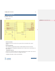
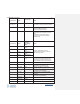
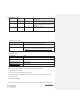
Table Of Contents
- COPYRIGHT INFORMATION
- TECHNICAL SUPPORT AND CONTACT INFORMATION
- Introduction
- Hardware Overview
- SMT Reflow Profile
- Host Board Design
- ThingMagic M3e Carrier Board
- TBD
- Programming for ThingMagic M3e
- Upgrading the ThingMagic M3e
- Verifying Application Firmware Image
- Host-to-Reader Communication
- Reader-to-Host Communication
- CCITT CRC-16 Calculation
- Power Modes
- Federal Communication Commission (FCC) Interference Statement
- User Manual Requirement
- End Product Labeling
- End Product Labeling
- Authorized Antennas
- Antennas
- Antennas
- Both the HF antenna and the LF antenna are attached to the Carrier Board.
- The HF antenna is embedded in the PCB of the Carrier Board.
- The LF antenna is connected to the Carrier Board.
- Powering Up and Connecting to a PC
- USB/RS232
- ESD Damage Overview
- Identifying ESD as the Cause of Damaged Readers
- Common Installation Best Practices
- Environmental

ThingMagic M3e User Guide
10
www.JADAKtech.com
30
I2C_SDA
In/Out
I2C bidirectional serial data - Unsupported in
Me3 Release 1
31
I2C_SCL
In
I2c Serial Clock -Unsupported in Me3 Release
1
32 ForceBootN In Consulted at power up. If LOW
the device will
stay in the bootloader and will not jump to the
application.
39 RFU NA – No connect Reserved for Future Use
Voltage and Current Limits
Specification
Limits
Input Low-level Voltage
0.8 V max to indicate low state; no lower than -0.3 V.
Input High-level Voltage 2.0 V min to indicate high state; 3.6 V max when module is powered
up, no more than 0.3 V to prevent damage when module is shut down
or turned off.
Voltage and Current
Specification
Limits
Output Low-level Voltage
0.3 V typical, 0.7 V maximum
Output High-level Voltage 3.0 V typical, 2.7 V minimum
Output Low-level Current
+2 mA maximum
Output High-level Current
-2 mA maximum
Control Signal Specification
The module can communicate to a host processor via a below mentioned interfaces-
1. All I/O’s are not 5 V tolerant.
2. UART with 3.3V logic levels from 9.6 to 460.8 kbps
The TTL logic level UART serial port, accessed on the edge “vias.” The TTL logic level UART supports
complete functionality.
TTL Level UART Interface
Only three pins are required for serial communication (TX, RX, and GND). Hardware handshaking is not