
User's Guide


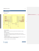
Table Of Contents
- COPYRIGHT INFORMATION
- TECHNICAL SUPPORT AND CONTACT INFORMATION
- Introduction
- Hardware Overview
- SMT Reflow Profile
- Host Board Design
- ThingMagic M3e Carrier Board
- TBD
- Programming for ThingMagic M3e
- Upgrading the ThingMagic M3e
- Verifying Application Firmware Image
- Host-to-Reader Communication
- Reader-to-Host Communication
- CCITT CRC-16 Calculation
- Power Modes
- Federal Communication Commission (FCC) Interference Statement
- User Manual Requirement
- End Product Labeling
- End Product Labeling
- Authorized Antennas
- Antennas
- Antennas
- Both the HF antenna and the LF antenna are attached to the Carrier Board.
- The HF antenna is embedded in the PCB of the Carrier Board.
- The LF antenna is connected to the Carrier Board.
- Powering Up and Connecting to a PC
- USB/RS232
- ESD Damage Overview
- Identifying ESD as the Cause of Damaged Readers
- Common Installation Best Practices
- Environmental

LIST OF FIGURES AND PHOTOS
www.JADAKtech.com
Module Pin-out ........................................................................................................................................... 2
Current Draw vs. DC Voltage and RF Output Level .................................................................................... 9
Module Output Power vs. Module Voltage ................................................................................................ 10
Power Consumption vs. DC Voltage and RF Output Level ....................................................................... 11
Output Power Accuracy vs. Channel Frequency ...................................................................................... 13
Accuracy of RF Output Power vs. Input DC Voltage ................................................................................. 13
Output Power Accuracy vs. Temperature ................................................................................................. 14
Module Dimensions .................................................................................................................................. 18
Tape Dimensions ..................................................................................................................................... 20
SMT Reflow Profile ................................................................................................................................... 21
Landing Pad and Heat-Sink Areas ........................................................................................................... 22
Carrier Board ............................................................................................................................................ 23
Carrier Board Schematic .......................................................................................................................... 25
Mount M3e on Heat Spreader Assembly .................................................................................................. 26
ThingMagic M3e Module on Carrier Board ............................................................................................... 56