
User's Guide


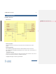
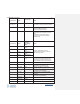
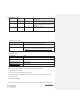
Table Of Contents
- COPYRIGHT INFORMATION
- TECHNICAL SUPPORT AND CONTACT INFORMATION
- Introduction
- Hardware Overview
- SMT Reflow Profile
- Host Board Design
- ThingMagic M3e Carrier Board
- TBD
- Programming for ThingMagic M3e
- Upgrading the ThingMagic M3e
- Verifying Application Firmware Image
- Host-to-Reader Communication
- Reader-to-Host Communication
- CCITT CRC-16 Calculation
- Power Modes
- Federal Communication Commission (FCC) Interference Statement
- User Manual Requirement
- End Product Labeling
- End Product Labeling
- Authorized Antennas
- Antennas
- Antennas
- Both the HF antenna and the LF antenna are attached to the Carrier Board.
- The HF antenna is embedded in the PCB of the Carrier Board.
- The LF antenna is connected to the Carrier Board.
- Powering Up and Connecting to a PC
- USB/RS232
- ESD Damage Overview
- Identifying ESD as the Cause of Damaged Readers
- Common Installation Best Practices
- Environmental

ThingMagic M3e User Guide
8
www.JADAKtech.com
Hardware Overview
Module Pin-out
Antenna Connections
ThingMagic M3e provides connections for a single HF antenna and simultaneously a single LF
antenna.
Antenna Requirements
The HF antenna port supports direct connection to external antenna circuit with 1 uH nominal.
The LF antenna port is compatible with a differentially-driven coil antenna with a nominal inductance of
505 uH nominal.
Digital/Power Interfaces
The edge “via” connections provide power, serial communications signals, an enable control, access to
the GPIO lines and antenna connections to ThingMagic M3e module.
ThingMagic M3e Digital Connector Signal Definition
2 Hardware Overview
Formatted: Normal, Space Before: 0 pt