Technical Guide AJ-V8 Engine and 5HP24 Transmission Introduction Published by Service Communications, Jaguar Cars Limited Publication Part No JJM 18 15 15/70, August 1996
AJ-V8/5HP24 Preface This Technical Guide introduces the new AJ V8 engine and 5HP24 transmission installed in the XK8 Sports car. It is intended to give Jaguar Dealer workshop personnel an overview of their construction and operation, and is for information purposes only. The contents of this Technical Guide must not be used as a reference source for servicing procedures; all servicing procedures must be in accordance with the appropriate Service Manual. This Technical Guide will not be updated.
Contents AJ-V8/5HP24 Subject Page Glossary Abbreviations 2 Introduction 3 Engine Basic Engine Engine Cooling Engine Lubrication Variable Valve Timing Air Intake System Fuel System Ignition System Crankcase Ventilation EGR System Engine Accessories Accessory Drive Engine Harness Engine Covers Engine Specifications 5 17 20 24 27 33 35 35 37 38 39 41 42 43 Engine Management ECM Electronic Throttle Fuel Pump Fuel Injection Ignition EVAP System Variable Valve Timing EGR System Engine Starting HO2S Heate
AJ-V8/5HP24 Glossary The following abbreviations are used in this document: 2 Abbreviation Description ABS A/C A/CCM BPM BHP ˚C CAN CDI DIN dc DTC ECM ECT EGR EMS EVAP ˚F ft HO2S in JDS lb lbf.
Introduction AJ-V8/5HP24 The AJ-V8 4.0 litre, engine is the first of a new family of Jaguar engines. Designed to give excellent performance, refinement, economy and low vibration levels it also conforms to the strictest emission legislation. Weighing only 200 kilograms (441 lb), the engine is shorter by 12 inches (300 mm) than the current AJ16 4.0 litre engine. Compression ratio is 10.75:1, with four valves per cylinder. The cylinder heads, block and bedplate are all cast aluminum.
4
Engine AJ-V8/5HP24 303-056 Basic Engine The AJ-V8 is an all new 90° V8 liquid cooled engine that gives refined and effortless performance. Constructed in aluminum alloy, the AJ-V8 introduces several innovative design features new to Jaguar engines, the most notable of these being: • a bedplate • nikasil coated cylinder bores • fracture split connecting rods • variable valve timing • aluminum alloy valve lifters • electronic throttle control.
AJ-V8/5HP24 Engine ENGINE STRUCTURE Cylinder Block 1 2 3 The cylinder block is an "enclosed V" design, which provides an inherently rigid structure with good vibration levels. Nikasil (a composition of nickel and silicon) coated cylinder bores provide good friction, heat transfer and piston noise levels.
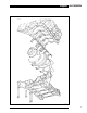
Engine AJ-V8/5HP24 CYLINDER BLOCK, CRANKSHAFT AND BEDPLATE 303-011 7
AJ-V8/5HP24 Engine Bedplate SEALANT TRACK ON BEDPLATE The bedplate is a structural casting bolted to the bottom of the cylinder block to retain the crankshaft. The use of a bedplate further improves rigidity. Iron inserts, cast into the main bearing supports of the bedplate, minimise main bearing clearance changes due to heat expansion. Two hollow dowels align the bedplate with the cylinder block. Beads of sealant seal the joint between the bedplate and the cylinder block.
Engine AJ-V8/5HP24 Connecting Rods and Pistons The connecting rods are manufactured in sinter forged steel. The bearing caps are produced by fracturing the opposing sides of the connecting rod at the bearing horizontal center-line. As well as being easier to manufacture, when re-assembled the fractured surfaces interlock to form a strong seamless joint. The cylinder position is etched on adjoining sides of the joint to identify matching connecting rods and bearing caps.
AJ-V8/5HP24 Engine STRUCTURAL SUMP AND OIL PAN Torque Converter Access 303-010 Starter and Drive Plate STARTER MOTOR The engine starter motor is installed at the rear right side of the engine, at the cylinder block to bedplate split line (for further details of the starter motor see Technical Guide, XK8 Introduction). The starter drive plate is attached to the rear of the crankshaft. A timing disc, for the engine speed sensor, is spot welded to the front face of the drive plate.
Engine AJ-V8/5HP24 TIMING DISC STARTER DRIVE PLATE 303-034 303-035 Cylinder Heads The cylinder heads are unique to each cylinder bank. Deep seated bolts, to reduce distortion, secure the cylinder heads to the cylinder block. Two hollow dowels align each cylinder head with the cylinder block. The cylinder head gaskets consist of a silicon beaded composite gasket with metal eyelets for the cylinder bores, similar to that on the AJ16 engine.
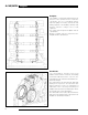
AJ-V8/5HP24 Engine A BANK CYLINDER HEAD Exhaust Camshaft Intake Camshaft Lifting Eye 303-047 Timing Gear Single row primary and secondary chains drive the camshafts of each cylinder bank. The primary chains transmit the drive from two sprockets on the crankshaft to variable valve timing units on the intake camshafts. The secondary chains transmit the drive from the variable valve timing units to sprockets on the exhaust camshafts.
Engine AJ-V8/5HP24 TIMING GEAR Secondary Chain Tensioner Primary Chain Secondary Chain Variable Valve Timing Unit Primary Chain Tensioner 303-016 / 017 13
AJ-V8/5HP24 Engine Timing Gear (Continued) A key locates the two drive sprockets on the crankshaft. The crankshaft's torsional vibration damper retains the sprockets in position. The variable valve timing units and the exhaust camshaft sprockets are non-interference, nonkeyed fits on their respective camshafts; the drive being transmitted by the face to face friction load produced by the valve timing unit/sprocket securing bolt. Each chain has an hydraulic tensioner operated by engine oil.
Engine AJ-V8/5HP24 Camshaft Covers The camshaft covers are manufactured from vinyl ester composite. The A bank camshaft cover incorporates an outlet for the full load engine breather. The B bank camshaft cover incorporates the engine oil filler cap and an outlet for the part load engine breather. Identical oil separators are incorporated below the breather outlet in each cover (see Crankcase Ventilation, page 35).
AJ-V8/5HP24 Engine Exhaust Manifold The thin-wall cast iron manifolds are unique for each cylinder bank. On engines with EGR, the A bank manifold has a connection for the transfer pipe. Spacers on the securing bolts allow the manifolds to expand and retract with changes of temperature while maintaining the clamping loads. Heat shields are integrated into the exhaust manifold gaskets.
Engine AJ-V8/5HP24 Engine Cooling The cooling system is a low volume, high velocity system with good warm-up and temperature profile characteristics. From the pump, the coolant flows into each bank of the cylinder block. In each bank, 50% of the coolant cools the cylinder bores and 50% is diverted through a bypass gallery. At the rear of the banks the two flows mix and enter the cylinder heads. The coolant then flows forwards to the outlet ports.
AJ-V8/5HP24 Engine Coolant Pump COOLANT PUMP The coolant pump is installed between the two cylinder banks, on the front face of the cylinder block. The pumping element is a shrouded composite impeller. Coolant escapes from seal breather holes in the housing if the pump's bearing seal fails. An O-ring and an edge bonded rubber/aluminum alloy gasket seal the pump to cylinder block interface. The O-ring seals the inlet port from the thermostat. The gasket seals the outlet ports into the cylinder banks.
Engine AJ-V8/5HP24 COOLANT HOSES Electronic Throttle EGR Valve Electronic Throttle A/C Heater Matrix 303-032 19
AJ-V8/5HP24 Engine Coolant Outlet Duct COOLANT OUTLET DUCT The composite coolant outlet duct connects to the outlet port of each cylinder head to provide a common connection point for the radiator top hose. It also incorporates connections for the coolant temperature sensor, the supply to the air conditioning heater matrix, and the bypass flow to the thermostat housing. An in-groove gasket seals each of the joints between the outlet duct and the cylinder heads.
Engine AJ-V8/5HP24 LUBRICATION SYSTEM 16 15 1 2 14 13 12 11 10 3 9 8 6 4 7 5 1. 2. 3. 4. 5. 6. 7. 8. Valve Lifter Supply Main Bearing Supply Connecting Rod Bearing Supply Bedplate/Cylinder Block Interface Oil Pick-up Pressure Relief Valve Oil Pressure Switch Oil Filter 9. 10. 11. 12. 13. 14. 15. 16.
AJ-V8/5HP24 Engine Oil Pick-up OIL PUMP The moulded composite oil pick-up is immersed in the oil reservoir to provide a supply to the oil pump during all normal vehicle attitudes. The castellated inlet allows the supply to be maintained even if the sump pan is deformed (eg. by “grounding”). A mesh screen in the inlet prevents debris from entering the oil system. Oil Pump The oil pump is installed on the crankshaft at the front of the engine.
Engine AJ-V8/5HP24 OIL SYSTEM COMPONENTS ON STRUCTURAL SUMP Pressure Switch Filter Pick-up 303-185
AJ-V8/5HP24 Engine Variable Valve Timing The variable valve timing system improves low and high speed engine performance, engine idle quality and exhaust emission. It is a two position system that operates on the intake camshafts only. There are 30° of crankshaft movement between the retarded and advanced positions. Engine oil pressure operates the system under the control of the ECM. For each intake camshaft there is a valve timing unit, a bush carrier assembly and a valve timing solenoid.
Engine AJ-V8/5HP24 VALVE TIMING UNIT Body and Sprocket Assembly Inner Sleeve Return Spring Piston Ring Gears 303-002 Bush Carrier The bush carrier contains oil passages that link the engine oil supply to the valve timing unit. A lug on the bush carrier locates in the central bore of the valve timing unit. Two hollow dowels at the bush carrier to cylinder block interface ensure the lug is accurately located. A scarf- jointed fibre ring seals the joint between the lug and the valve timing unit.
AJ-V8/5HP24 Engine Valve Timing Solenoid VALVE TIMING SOLENOID The valve timing solenoid controls the position of the shuttle valve in the bush carrier. A plunger on the solenoid extends when the solenoid is energised and retracts when the solenoid is deenergised. Operation 303-004 When the valve timing solenoids are deenergised, the coil springs in the bush carriers position the shuttle valves to connect the valve timing units to drain.
Engine AJ-V8/5HP24 This momentarily energises the valve timing solenoids to allow a spurt of oil into the valve timing units. The lubrication pulse occurs once every 5 minutes. Note: With the vehicle stationary and the hood open, operation of the valve timing solenoids may be audible when the lubrication pulse occurs at engine idle speed.
AJ-V8/5HP24 Engine Electronic Throttle Vacuum Actuator The electronic throttle enables the ECM to control the flow of air into the engine.
Engine AJ-V8/5HP24 ELECTRONIC THROTTLE Vacuum Actuator Vent dc Motor Coolant Inlet Coolant Outlet Thermostatic Air Valve 303-067 Springs The input shaft spring and the mechanical guard spring oppose movement in the throttle open direction, and provide the "feel" of the accelerator pedal. The throttle valve spring and the drive gear spring oppose movement in the throttle closed direction.
AJ-V8/5HP24 Engine At idle, the ECM controls engine speed using the restricted throttle valve movement available between the mechanical guard (open limit) and a factory set stop on the dc motor drive gear (closed limit). When cruise control is engaged, the ECM calculates the required throttle valve opening and operates the vacuum system connected to the vacuum actuator. The vacuum actuator then turns the mechanical guard to a position that allows the required throttle valve opening.
Engine AJ-V8/5HP24 ELECTRONIC THROTTLE OPERATING MODES 5 4 Normal 6 3 2 4 3 1 1 Cruise Crontrol 5 2 6 4 Mechanical Guard 3 2 Spring Force 1 303-080,/081/082 31
AJ-V8/5HP24 Engine INDUCTION ELBOW Fuel Tank Vacuum and Pressure Relief Valve Connection Part Load Breather/ EVAP Valve Vacuum Connection Fuel Pressure Regulator/ Cruise Control Vacuum Connection Brake Booster Vacuum Connection 303-033 Induction Elbow SECTION THROUGH INTAKE MANIFOLD The induction elbow provides the interface between the electronic throttle and the intake manifold. Connections on the induction elbow provide vacuum take-offs for various services.
Engine AJ-V8/5HP24 Fuel System Fuel injectors, controlled by the ECM, are installed in the fuel rails on each side of the intake manifold. A cross-over pipe connects the two fuel rails together at the front of the manifold. A test valve in the cross-over pipe allows the fuel rail to be pressurised and depressurised during servicing and troubleshooting. A pressure regulator on the rear of the right fuel rail controls the pressure in the fuel rails.
AJ-V8/5HP24 Engine Fuel Injectors FUEL INJECTOR Eight, side fed, dual straight jet, fuel injectors are installed in the fuel rails. The injectors are electromagnetic solenoid valves controlled by the ECM. Two O-rings seal each injector to manifold interface. The fuel jets from the injectors are directed onto the back of the intake valves. Pressure Regulator The pressure regulator is a diaphragm operated valve that regulates fuel rail pressure at 2.9 bar (42.05 psi) above intake manifold pressure.
Engine AJ-V8/5HP24 Ignition System The ignition system consists of two ECM controlled ignition amplifier modules, which each supply four spark plug mounted ignition coils. The 14 mm spark plugs, one per cylinder, locate in recesses down the center-line of each cylinder head. The on-plug ignition coils are secured to the camshaft covers. The engine harness connects the on-plug ignition coils to the ignition amplifiers located on the vehicle body. A composite cover fits over the on-plug coils.
AJ-V8/5HP24 Engine CRANKCASE VENTILATION SYSTEM Part Load Breather Hose Connector Full Load Breather Hose Connector 303-065/077/079 36
Engine AJ-V8/5HP24 EGR System The EGR system is controlled by the ECM and consists of an EGR valve and a transfer pipe. The EGR valve is a 4 pole stepper motor installed on the rear of the induction elbow. The valve is cooled by the coolant return from the electronic throttle. The transfer pipe connects the right exhaust manifold to the EGR valve.
AJ-V8/5HP24 Engine Engine Accessories All engine accessories are rigidly mounted to improve refinement, ie. there are no shock mounts. Accessory mounting brackets on the left and right sides of the engine support the A/C compressor/ PAS pump and the generator respectively. Dowels between the accessory mounting brackets and the engine ensure the accessory pulleys are accurately aligned with the accessory drive belt (for further details of the accessories see Technical Guide, XK8 Introduction).
Engine AJ-V8/5HP24 ENGINE ACCESSORIES AND DRIVE BELT PAS Pump Generator A/C Compressor 303-018 Accessory Drive A single seven ribbed belt drives all the engine mounted accessories. The torsional vibration damper on the front of the crankshaft drives the belt. An automatic tensioner, located on the left accessory mounting bracket, keeps the belt at the correct tension. An idler pulley on the right accessory mounting bracket increases the wrap angle around the generator pulley.
AJ-V8/5HP24 Engine ENGINE HARNESS 1 20 19 18 3 2 17 4 16 15 5 14 13 6 12 7 8 11 9 10 Connectors 1. PI032, B Bank VVT solenoid 2. PI027, B Bank Knock Sensor 3. PI004, Engine Coolant Temperature Sensor 4. PI026, A Bank Knock Sensor 5. PI031, A Bank Valve Timing Solenoid 6. PI035, MAFS (On vehicle) 7. PI050, Generator 8. PI040, Oil Pressure Switch 9. PI018-PI021, A Bank Ignition Coils 1-4 PI022-PI025, B Bank Ignition Coils 1-4 10. PI006, Throttle Position Sensor 11. 12. 13. 14. 15. 16. 17. 18. 19. 20.
Engine AJ-V8/5HP24 Engine Harness The engine harness links engine mounted electrical components to the vehicle's engine management harness. The connectors that interface with the engine management harness are attached to a bracket on the transmission housing. Integral nylon fasteners attach the harness to the engine. Connectors on component flying leads are attached to engine mounted brackets.
AJ-V8/5HP24 Engine Engine Covers Engine covers are installed over the fuel injectors. The covers are a push fit, held in position by mating studs and grommets on the covers and the engine. The rubber grommets isolate the covers from the engine to prevent noise. A sleeve connects the covers together at the rear.
Engine AJ-V8/5HP24 Engine Specifications Configuration Cylinder Head Valve Clearances (Cold): Intake Exhaust Spark Plug Type: Spark Plug Gap: Firing Order Bore Stroke Displacement Compression Ratio Maximum Power (DIN) Maximum Torque (DIN) Maximum Speed (Limited) Coolant Type Coolant Volume: Engine Only Complete System Oil Specification: Oil Volume: Weight (With Accessories) 90° V8 Dual overhead camshafts, 4 valves per cylinder 0.18 to 0.22 mm (0.007 to 0.009 in) 0.23 to 0.27 mm (0.009 to 0.
AJ-V8/5HP24 Engine Management ECM ECM 303-118 44 The engine management system is controlled by the ECM, which is installed in the control module enclosure in the engine compartment. The ECM provides optimum control of the engine under all operating conditions. It also incorporates a comprehensive monitoring and diagnostic capability. Software variations ensure that the system complies with the latest diagnostic and emissions legislation of the destination market.
Engine Management AJ-V8/5HP24 Inputs and Outputs Inputs and outputs are directed to and from the ECM through hard-wired connections and the CAN and ISO 9141/2 (Serial Communication) data buses contained in the engine management harness (for further information on the data buses, refer to the Technical Guide, XK8 1997 Model Year Introduction).
AJ-V8/5HP24 Engine Management ECM PIN CONNECTIONS 1 7 6 12 EM014 1 12 11 22 1 11 17 27 10 16 26 34 EM015 EM013 1 4 7 7 12 11 18 16 6 11 17 22 EM012 1 5 8 12 1 9 14 22 8 13 21 28 EM011 EM010 303-129 Connector/ Pin Circuit Pin Circuit Pin Circuit EM013 001 Fuel pump control 002 EMS programming 003 Cruise control switch LED 004 ) 005 ) 006 ) 007 ) Not used 008 ) 009 ) 010 ) 011 VSV 3 012 VSV 1 013 014 015 016 017 018 019 020 021 022 023 024 VSV 2 Throttle motor relay Radiator cooling
Engine Management AJ-V8/5HP24 ENGINE HARNESS PIN CONNECTIONS 1 5 1 4 9 6 5 10 13 10 11 16 17 22 23 26 27 28 29 30 31 34 35 40 41 46 47 52 53 57 PI001 PI002 PI002 PI001 303-061/136/137 Engine Harness to Engine Management Harness Pin Connections Connector/ Pin Circuit PI001 001 Throttle position sensor 2 002 A/C compressor lock sensor ground 003 Throttle position sensor 1 004 Shield ground (throttle position sensor) 005 ECT sensor 006 Sensor ground (ECT, accelerator pedal po
AJ-V8/5HP24 Engine Management Connector/ Pin Circuit Pin Circuit Pin Circuit PI002 001 002 003 004 005 006 007 008 009 010 Throttle motor (-) Throttle motor (+) ) ) Not used ) 011 012 013 Not used Generator regulator supply Not used ) ) Not used ) ) Injector supply CAN Messages Messages on the CAN data bus used or output by the ECM are detailed below: Note: This list does not include network monitoring or diagnostic related messages.
Engine Management AJ-V8/5HP24 Sensors Engine management sensors that input to the ECM are detailed below: OXYGEN SENSORS Barometric Pressure Sensor The barometric pressure sensor is installed in the ECM. It senses ambient pressure in the engine management enclosure of the engine compartment. H02S HO2S A HO2S is installed in the intake end of each catalytic converter. They provide inputs proportional to the oxygen content of the exhaust gases leaving the engine.
AJ-V8/5HP24 Engine Management Camshaft Position Sensor The camshaft position sensor is installed in B bank cylinder head at the rear of the intake camshaft. It is a variable reluctance sensor that provides an input of intake camshaft position. ECT Sensor The ECT sensor is installed in the coolant outlet duct. It provides an input of coolant temperature at the cylinder head outlets. Engine Speed Sensor The engine speed sensor is installed at the rear of the bed plate.
Engine Management AJ-V8/5HP24 ENGINE SENSORS Knock Sensors ECT Sensor Camshaft Position Sensor Engine Speed Sensor 303-127 51
AJ-V8/5HP24 Engine Management ENGINE MANAGEMENT SCHEMATIC ECM Inputs and Outputs 1. Intake Air Temperature Sensor 2. MAFS 3. Throttle Position Sensor 4. (Throttle) dc Motor 5. EGR Valve 6. Fuel Injector 7. Camshaft Position Sensor 8. On-plug Ignition Coil 9. H02S 10. 02S 11. Engine Speed Sensor 12. Accelerator Pedal Position Sensor 13. Mechanical Guard Position Sensor 14. ECT Sensor 15.
Engine Management AJ-V8/5HP24 Electronic Throttle The electronic throttle enables the ECM to perform the following functions: • engine air flow (ie.
AJ-V8/5HP24 Engine Management Vehicle Cruise Control CRUISE CONTROL MASTER SWITCH 303-132 CRUISE CONTROL STEERING WHEEL SWITCHES 303-131 54 The ECM operates the vehicle cruise control system, in all forward gears, in response to driver inputs through the master, SET+, SET-, CANCEL and RES switches. When the master switch is pressed, two 12 V ignition supplies are connected to the ECM, one direct and one via the brake switch. The LED in the switch comes on to indicate the system is armed.
CRUISE CONTROL SCHEMATIC B+ Ignition Driver’s Facia Fuse Box F14 To Dimmer Switch ECM Master Switch Ignition Switched Ground Steering Wheel Switches SET+ Accelerator Pedal Position and Mechanical Guard Position Sensors Brake Cancel Switch Brake Switch VSV 2 Throttle Valve Position Sensor VSV 3 CANCEL Vacuum Actuator RES M dc Motor VSV 1 Parking Brake Switch Check Valve Engine Speed Sensor -VEHICLE SPEED -TRACTION STATUS -GEAR POSITION SELECTED Reservoirs CAN 55 303-133 Engine Management A
AJ-V8/5HP24 Engine Management Once cruise control is engaged, a further momentary press of the SET+ or SET- switch increments or decrements the set speed by 1.6 km/h (1.0 mph). The ECM then accelerates or decelerates the vehicle to the new set speed. The ECM stores a maximum of five incremental or decremental commands at any one time. Once the ECM has actioned the first stored command, a further command can be added.
Engine Management AJ-V8/5HP24 CRUISE CONTROL VACUUM SYSTEM Reservoirs Check Valve VSV 2 VSV 1 VSV 3 303-121 Stability/Traction Control If the CAN- TORQUE REDUCTION THROTTLE message from the brake control module requests torque reduction, the ECM reduces the throttle valve opening. It also changes the CANTRACTION ACKNOWLEDGE message to confirm that torque reduction is in progress.
AJ-V8/5HP24 Engine Management Fuel Injection FUEL PUMP CONTROL B+ Battery B+ Ignition Fuel Pump Relay F7 ECM Trunk Fuse Box Fuel Pump 303-134 Fuel Pump An output from the ECM controls the relay that operates the fuel pump. At ignition on, the pump will operate for 2 seconds without the ignition switch being set to crank, after which time the pump will be de-energized. Similarly, if the engine stops with the ignition on, the pump will be deenergized after 2 seconds.
Engine Management AJ-V8/5HP24 Starting Engine Overspeed Protection The fueling start strategy operates independent of accelerator pedal position or movement, with the exception of a wide open throttle. The ECM produces steady state running at the target idle speed within 2 seconds of firing, after an overshoot of 200 to 300 RPM maximum.
AJ-V8/5HP24 Engine Management Base Ignition Map A base ignition map contains optimum timing for a nominal engine throughout the engine speed and load ranges. Corrections are then added to adjust for specific operating conditions. Temperature Corrections Corrections are added to the ignition timing to compensate for variations in intake air temperature and engine coolant temperature. changes the CAN-TORQUE REDUCTION ACKNOWLEDGE message to the TCM to trigger the gear shift.
Engine Management AJ-V8/5HP24 Variable Valve Timing EGR System VARIABLE VALVE TIMING MAP Engine Load The ECM energizes the valve timing solenoids to advance the intake valve timing and de-energizes them to retard it. The ECM uses engine load and speed maps to decide when to advance and retard the timing. The maps incorporate hysteresis for both engine load and speed to prevent "hunting".
AJ-V8/5HP24 Engine Management H02S Heaters The ECM energizes the heater elements of the HO2S during engine warm-up to shorten the time it takes for them to produce accurate outputs. Instrument Cluster The instrument cluster uses CAN messages from the ECM to operate the trip computer, tachometer, engine coolant temperature gauge and the BRAKE, CHECK ENG and general warning lamps. Note: The CHECK ENG lamp is commonly known as the MIL.
Engine Management AJ-V8/5HP24 To counteract the increase in engine coolant temperature that occurs after the engine stops, at ignition off: • if the fans are already on, the ECM keeps them on for 5 minutes, or until the ECT decreases to a pre-determined value, whichever occurs first • if the fans are off, the ECM determines, from ECT and intake air temperature inputs, if the fans need to be switched on.
AJ-V8/5HP24 Engine Management Additional Input Checks Input Additional Strategy Action, Substitute or DefaultValue Accelerator pedal position (x 2) and mechanical guard position Accelerator pedal position input 1 compared to accelerator pedal position input 2. Both accelerator pedal position inputs compared to mechanical guard position input. If one input fails, the input of the other two is used. If two inputs fail, ECM adopts fixed throttle mode. Throttle position (x 2) 1 compared to input 2.
Transmission AJ-V8/5HP24 Introduction The new ZF 5HP24 automatic transmission system features five forward gears and one reverse gear. It also features a filled-for-life oil system. Gearshift management is achieved using a Transmission Control Module (TCM).
AJ-V8/5HP24 Transmission Tecnical Data Transmission weight including fluid and torque converter Oil Type Oil Capacity Gear Ratios 95.8 kg (211 lbs) ATF Esso LT71141 10 liters (2.645 US. gals) 1st Gear 3.571:1 2nd Gear 2.202:1 3rd Gear 1.505:1 4th Gear 1.000:1 5th Gear 0.803:1 Reverse 4.095:1 Gearshifting Driver gear selection is transmitted from the gear selector lever by cable to a lever fitted to a selector shaft in the transmission casing. This shaft moves the manual valve and the rotary switch.
Transmission AJ-V8/5HP24 Electrical Description mistaken for an oil leak. BAYONET CONNECTOR EM046 Electrical Connections Bayonet Connector A round, 16-pin, bayonet electrical connector is fitted at the rear left-hand side of the transmission which communicates with the 5 pressure regulators, 3 shift solenoids, oil temperature sensor and the input and output 1 3 6 10 14 2 5 9 13 16 EM 046 BLACK 307-023 Connector/ Pin Circuit Pin Circuit Pin Circuit shaft speed sensors.
AJ-V8/5HP24 Transmission Management Transmission Management The transmission management system uses both analogue and digital signals, to control the operation of the transmission. Digital signals are processed by the TCM to and from the vehicle multiplex network. Other input/output analogue signals are hardwired to the TCM. This information is used primarily by the TCM to decide which shift program to implement, which gear to select and for shift energy management.
Transmission Management AJ-V8/5HP24 Gear Shift Interlock Fault Monitoring/Diagnostics Gear shift interlock is controlled by the BPM, part of the SCP network. The gearshift release will only be activated when the ignition is in position II, transmission is in Park and the brake pedal is depressed. Once transmission is out of Park, the brake pedal has no effect on gearshifting and the interlock is disabled. The TCM constantly monitors the transmission system for faults.
AJ-V8/5HP24 Transmission Management TCM T.C.
Transmission Management AJ-V8/5HP24 Can Messages Messages on the CAN data bus used or output by the TCM are detailed below: Note: This list does not include network monitoring or diagnostic related messages.
AJ-V8/5HP24 Service Tools New Tools The table below lists the new service tools required for the AJ V8 engine. These are in addition to the tools already in use on 6 and 12 cylinder engines, some of which can also be used on the AJ V8. Details of new service tools for the 5HP24 transmission will be supplied at a later date.