Compact Monochrome Megapixel Progressive Scan Camera CV-A1 Operation Manual Camera: Revision B Manual: Version 1.2 A1manB12oct08.
CV-A1 Table of Contents 1. General......................................................................................................... 2 2. Standard Composition ....................................................................................... 2 3. Main Features ................................................................................................. 2 4. Locations and Functions..................................................................................... 3 5. Pin Assignment........
CV-A1 1. General The CV-A1 is a monochrome progressive scan 1/2” CCD camera with 1.4 Megapixel resolution. It is designed for automated inspection, featuring a small housing and a wide range of unique functions. The asynchronous trigger can be set to work in several modes, to allow such functions as pulse width controlled shutter, programmable shutter speed and long time integration. To obtain higher frame rates, the camera has partial scanning and both horizontal and vertical binning.
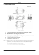
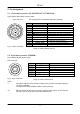
CV-A1 4. Locations and Functions Fig. 1. Locations. 1. 2. 3. 4. 5. 6. 7. Note: *1) 12 pin Hirose connector for frame grabber interfacing and power (12V DC). BNC connector for video output. VS 1.0 Vpp 75 Ohm. 6 pin Hirose connector for trigger input and RS-232C control interface. Gain potentiometer for manual gain setting. Mounting holes, 8 x M3. For precision mounting use only the 4 holes located at the forward part of the bottom plate. 1/2” interline-transfer type CCD sensor.
CV-A1 5. Pin Assignment 5.1. 12-pin Multi-connector (DC-IN/VIDEO OUT, EXT.HD/VD IN) Type: HR10A-10R-12PB-01 (Hirose) male Seen from rear 9 1 2 8 10 11 3 4 7 12 6 5 Pin configuration is compatible with EIAJ standard Pin no. 1 2 3 4 5 6 7 8 9 10 11 12 Signal GND +12 V DC input GND Video output GND HD input/HD output VD input/VD output GND Pixel clock output WEN output Trigger input GND Remarks Parallel with the BNC connector. *) SW2.1 on for 75Ω. SW1.1 on for HD out. *) SW2.2 on for75Ω. SW1.
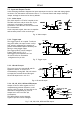
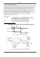
CV-A1 5.3. Input and Output Circuits In the following schematic diagrams the input and output circuits for video and timing signals are shown. For alternative connections refer to “7.4. Internal Switch and Jumper Settings.” Jumper settings are shown as for factory default. 5.3.1. Video output The video output is a 75 Ω DC coupled circuit. The BNC connector and pin #4 on the 12-pin connector is in parallel. Avoid double termination. The video DC level is shown with 75 Ω termination.
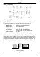
CV-A1 5.4. CV-A1 Block Diagram Fig. 8. Block diagram. 6. Functions and Operations 6.1. Basic functions Some of the primary camera functions need a general introduction before the operation modes are described. The list below shows the primary functions from the command list. SM SH PE SC BI TR Shutter Mode Shutter Speed Programmable Exposure Scanning Format Binning Trigger Mode HC HD Accumulation Normal shutter, Programmable Exposure Off to 1/200,000 second 1.3 H to 1023.
CV-A1 Binning mode BI is a function where the signal charge from 2 or more adjacent pixels are added together and read out as one pixel. A resulting full frame with lower resolution can be read out with a higher rate. By adding 2 pixels together, the sensitivity is doubled. The CV-A1 has both vertical and horizontal binning. With V binning the pixel charge from 2 adjacent lines are added together in the horizontal ccd register. It is done by double pulses to the vertical ccd register.
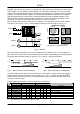
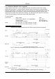
CV-A1 6.2. Input-output of HD/VD Signals In the default setting the camera will accept external HD/VD signals on pin 6 and 7 of the 12 pin Hirose connector. If external HD/VD is applied, the camera will synchronize to it. If no external sync signals are applied, the camera will operate with its internal x-tal controlled sync. The camera scanning system should be set to the same as the external connected sync. In fig. 13 below, the time requirements to relation between VD and HD are shown.
CV-A1 6.3. Continuous Operation (Non triggered) Trigger Mode Normal. TR=0. It is for applications where the camera is continuous running without external trigger. In normal mode the shutter mode can be normal or programmable exposure. (SM=0 SM=1). The shutter will work in all 16 steps up to 1/200,000 second or with the programmable exposure in 1023 steps. In partial scanning and binning modes, shutter times longer than the actual frame time has no meaning. The exposure will be equal the frame time.
CV-A1 6.4. External Trigger Modes This camera has 6 external asynchronous trigger modes, which can be set by RS-232C commands. 1. 2. 3. 4. 5. 6. Edge Pre-select Mode.TR=1 Pulse Width Control Mode. TR=2 Frame Delay read out mode. TR=3 Long Time Exposure Mode. TR=4 Start/stop Mode. TR=5 Smearless Read out mode. TR=6 Pre-selected exposure. (SM=0, SM=1) Pulse width controlled exposure. (HC=0, HC=1) PWC exposure read out by ext. VD. (HC=0, HC=1) Exposure is interval between ext. VD.
CV-A1 6.5. Edge Pre-select Mode The exposure starts at the first HD pulse after the trigger leading edge. It stops and is read out after the duration of the shutter time selected. It can be the first 9 step in normal or 1023 steps in programmable shutter. SM=0 or SM=1. Shutter selections SH ≥10 will result in 1/12,000 sec. This mode will operate with full and partial scanning and with all binning modes.
CV-A1 6.6. Pulse Width Control Mode In this mode the exposure starts from the leading edge of the trigger pulse. It stops at the trailing edge of the trigger pulse, and the resulting video is read out. The accumulation can be either H synchronous or H asynchronous. HC=0 or HC=1. In H synchronous mode the accumulation starts at the first HD pulse after the leading edge of the trigger. It can result in <1H jitter if the trigger is not synchronized to H.
CV-A1 6.7. Frame-delay read out Mode In this mode the exposure starts from the leading edge of the trigger pulse. It stops at the trailing edge of the trigger pulse. The accumulation can be either H synchronous or H asynchronous. HC=0 or HC=1. In H synchronous mode the accumulation starts at the first HD pulse after the leading edge of the trigger. In H asynchronous mode the accumulation starts immediately after the leading edge of the trigger. (The internal H is not reset.
CV-A1 6.8. Long Time Exposure Mode The exposure time is the interval between 2 external VD pulses sent to the VD input. The exposure starts after the input of a VD, and it ends after the next VD input, which again starts a new exposure. The interval between the external VD pulses (exposure time) can be from V to ∞. Thermal and dark current noise will increase by accumulation time, therefore the exposure time is not recommended to exceed 2 seconds (or 30 V periods).
CV-A1 6.9. Start/Stop Mode The exposure is controlled by the interval between the external trigger pulse and an external VD pulse. The exposure start at the first HD pulse after the trigger leading edge, and it stops after the rising edge of the VD. An EEN pulse will indicate the active accumulation time, and a WEN pulse indicates that the resulting video is being read out. The shortest exposure time in this mode is >1.3H. The longest exposure time is <2000 H.
CV-A1 6.10. Smearless Mode This mode will reduce the unwanted smear signal from a highlighted scene when a short exposure time is used. The trigger mode is like edge pre-select, but a dummy readout is performed before the active accumulation is started. It will remove the smear above the highlighted parts in the image, but there is still smear left below highlighted areas. The trigger leading edge will start the dummy readout. It takes 54 H before the exposure starts.
CV-A1 6.11. Other Functions. Gain and analogue settings. !! Do not adjust these settings unless you have knowledge to video adjustments !! The video gain can be set to AGC or manual. In AGC mode the video level is kept constant by the automatic gain control circuit within a 12 dB range. Normal 700 mVpp ±30 mV. The level can be adjusted with AGC level. In manual gain mode, either the gain level or the rear potentiometer can adjust the level. Setup level.
CV-A1 7.2. CV-A1 RS-232C command list. EB ST HP VN ID MD UD SC Command Name Format A – General settings and useful commands Echo Back EB=[Param.] Camera Status request ST? Online Help request HP? Firmware version VN? Camera ID request ID? Model name request MD? User ID UD=[Param.] B – Timing and shutter related commands Scanning format SC=[Param.] TR Trigger mode TR=[Param.] SM SH Shutter mode Shutter speed SM=[Param.
CV-A1 7.3. Camera Control Tool for CV-A1 From www.jai.com CV-A1 Camera Control Tool for Windows 98/NT/2000 can be downloaded. The control tool contents a camera control program and tools for making your own program. Below the different windows are shown. Control Bar Windows for all functions Fig. 26. Windows from Camera Tools.
CV-A1 7.4. Internal Switch and Jumper Settings For VD and HD input/output and termination refer to “6.2. Input-output of HD/VD Signals.” For alternative connections of pin #10 and #11 on 12-pin connector, jumper JP1, JP2, JP3, JP4 and JP5 can be used. Refer “5.3. Input and Output Circuits.” Jumper setting for alternative pin configuration for M-series camera emulating is shown below. Pin # 9 9 10 10 11 11 Function PCLK out No connection WEN out Ground Ext.
CV-A1 9. Specifications Specifications Scanning system Pixel clock Line frequency Frame rate for full frame CCD sensor Sensing area for video out Effective pixels Pixels in video output Cell size Resolution horizontal Sensitivity on sensor S/N ratio Video output CV-A1 Progressive 1068 lines 16.037 frames/sec. 28.63636 MHz 17.127 kHz (1672 pixel clock/line) 16.037 frames/sec. (1068 lines/frame) 1/2” progressive monochrome IT CCD. Sony ICX205AL-6 6.42 (h) x 4.
CV-A1 10. Appendix 10.1. Precautions Personnel not trained in dealing with similar electronic devices should not service this camera. The camera contains components sensitive to electrostatic discharge. The handling of these devices should follow the requirements of electrostatic sensitive components. Do not attempt to disassemble this camera. Do not expose this camera to rain or moisture. Do not face this camera towards the sun, extreme bright light or light reflecting objects.
CV-A1 11. Users Record Camera type: CV-A1 Revision: (Revision B) Serial No. …………….. Users Mode Settings Users Modifications DECLARATION OF CONFORMITY AS DEFINED BY THE COUNCIL DIRECTIVE 89/336/EEC EMC (ELECTROMAGNETIC COMPABILITY) WE HEREWITH DECLARE THAT THIS PRODUCT COMPLIES WITH THE FOLOWING PROVISIONS APPLYING TO IT. EN-50081-1 EN-50082-1 Company and product names mentioned in this manual are trademarks or registered trademarks of their respective owners.