Digital Monochrome Quad Speed CMOS Progressive Scan Camera CV-A33CL Operation Manual Camera: Revision A Manual: Version 1.0 A33Manualsep09.
CV-A33CL Table of Contents 1. General ........................................................................................................2 2. Standard Composition ......................................................................................2 3. Main Features ................................................................................................2 4. Locations and Functions ...................................................................................3 5. Pin Assignment............
CV-A33CL 1. General The CV-A33CL is a digital CMOS camera designed for automated imaging applications, featuring high speed within a uniform and compact housing. The high-speed shutter function, asynchronous random trigger mode and partial scan mode, with window of interest, allows the camera to capture high quality images of fast moving objects with a high frame rate. The CV-A33CL features the Camera Link standardized multiplexed signal output interface.
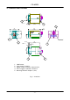
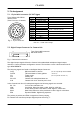
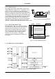
CV-A33CL 26 (1 .02 ) 4. Locations and Functions 5 4xM3 Depth 4 4M - 3深4 5 (0 .2 ) 50 (1 .97 ) 5 4 44 (1 .73 ) 58 (2 .28 ) 7 .6 (0 .3 ) DG I ITAL I /O 17 .5 (0 .69 ) 35 (1 .38 ) DC IN / TR IG U4-40 コネクター固定ネジ CM - oun t 2 50 (1 .97 ) (0 .2 ) 5 4xM3 6 M3深4 -Depth 4 3 機銘版 8 (0 .31 ) 26 (1 .02 ) 1 5 1. 2. 3. 4. 5. 5 CMOS sensor Lens mount (C-mount) Digital output connector (Camera Link) DC in/Trigger in/RS-232C connector Mounting holes M3. Depth 4. (10x) Fig. 1.
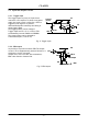
CV-A33CL 5. Pin Assignment 5.1. 12-pin Multi-connector (DC-IN/Trigger) Type: HR10A-10R-12PB-01 (Hirose) male. (Seen from rear of camera.) 9 1 2 8 10 11 3 4 7 12 5 6 Fig. 2. 12-pin connector. Pin no. 1 2 3 4 5 6 7 8 9 10 11 12 Signal GND +12 V DC input GND N/C GND RXD in TXD out GND EEN out Trigger input N/C GND Remarks RS 232C. Or via Camera Link by internal SW200 on PK8378A (Off=HR) And via Camera Link Or via Camera Link.
CV-A33CL 5.3. Input and Output Circuits 5.3.1. Trigger input The trigger inputs on pin #10 12 pin Hirose connector is AC coupled. To allow a long pulse width, the input circuit is a flip flop, which is toggled by the negative or positive differentiated spikes caused by the falling or rising trigger edges. The trigger polarity can be changed. Trigger input level 4 V ±2 V. It can be 75Ω terminated by internal SW300 on PK8388A. The trigger inputs can be changed to Camera Link input.
CV-A33CL 5.3.3. Camera Link interface The video output is Camera Link with 10 or 8 bit video placed in a base configuration. The digital output signals follow the Camera Link standardized multiplexed signal output interface. The Camera Link output driver is NS type DS90CR285MTD. The data bits from the digital video, FVAL, LVAL, DVAL and EEN are multiplexed into the twisted pairs, which are a part of the Camera Link. Trigger signals and the serial camera control are feed directly through its own pairs.
CV-A33CL 6. Functions and Operations In the following the format shown in “7.3. CV-A33CL command list” are used for function commands and parameters. 6.1. Basic functions The CV-A33CL camera is a progressive scan camera with 10 or 8 bit video output in single channel Camera Link. Programmable partial scan, where the start line and the number of lines can be selected with 1 line increment is also available.
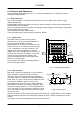
CV-A33CL 6.1.3. Column Process The voltage signal from a single pixel is send to the Columns column amplifier trough the 4 to 1 multiplexer. After 10 bit the S/H circuit, the offset and gain calibrating is video To shift Offset Register perform. A 10 bit A/D converter send the digital pixel Amp S/H Gain A/D through calibr 1 to 4 signal to the digital horizontal shift register by a 1 to 4 multiplex multiplexing.
CV-A33CL 6.1.6. Window of Interest If a higher frame rate is wanted, it is possible to change the CMOS sensors sensing area to the window of interest. WS =1 for windows scan. The X,Y start coordinate, the window width and height can be programmed. WX can be in the range 0 to 657 WY can be in the range 0 to 490 WW can be in the range 2 to 659. (WX + WW ≤ 659) WH can be in the range 3 to 493. (WY + WH ≤ 493) The frame rate will not increase if the width WW is reduced.
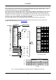
CV-A33CL 6.2. Sensor layout and timing. 6.2.1. Effective image format The drawing below shows the effective pixels on the CCD array with respect to pixels and lines as it is used in the timing and video read out. (0, 0) Minimum window size 3 2 493 Active Pixel Array (658, 492) 659 Fig. 13. Effective image layout 6.2.2. Vertical timing Normal mode. Full frame. 1 LVAL = 16.825 µs 1 FVAL per i od 502L 498L 4L FVAL LVAL ( When t he ex pos ur e i s max .
CV-A33CL 6.2.4. LVAL a-synchronous accumulation The CV-A33CL has LVAL a-synchronous accumulations only. The accumulation will start 28 µsec. after the trigger leading edge. EEN will indicate the accumulation time. When the accumulation stops after the selected shutter time, the LVAL phase is reset and restarted. 1 LVAL = 16.825 µsec. 16.8 µsec. LVAL Trigger Accum Delay 28 µsec. EEN Fig. 16.
CV-A33CL 6.2.5. Timing for window of interest With WS=1, the X and Y start coordinates (WX and WY), and the width and height (WW and WH) for the window of interest can be programmed with 1 pixel interval. The minimum window size is 2(h) x 3 (v). If the window is specified outside the full image area, it will be placed up to the right or low limit as shown in fig 17. right. Figures marked with (*) in the timing diagrams below will change with other window settings.
CV-A33CL 6.3. Input/Output of Timing Signals 6.3.1. Input of Timing Signals It is not possible to synchronize the camera from an external sync source except by an extern trigger pulse. The camera will always run with its internal X-tal controlled timing. Trigger input through Camera Link. TI=0 Trigger input as TTL on pin #10 on 12 pin Hirose. TI=1 The trigger polarity is active low. TP=0 Trigger input can be changed to active high.
CV-A33CL 6.4.1. Continuous Operation (Non triggered) Mode settings can be done with RS-232C. Trigger Mode Normal. TR=0. It is for applications where the camera is continuous running without external trigger. The shutter mode can be normal or programmable exposure. (SM=0, SM=1). The shutter will work in all 8 steps up to 1/20,000 second or with the programmable exposure in 2 to 493 steps. In programmable exposure the actual exposure is 1 LVAL less than the PE value.
CV-A33CL When ( the exposu re ism in . (PE=2 ) ) 1 LVAL = 16.825µs TRG 2L 1 FVAL pe r iod 502L 498L 2L FVAL LVAL 27 .6 μS Exposu re pe r iod EEN 5L …… 48 488 499 490 491 2 DATA OUT 0 1 2 3 4 …… E f fec t ive L ines 493L DVAL Fig. 20. Vertical timing for edge pre-select min. exposure When ( the exposu re ismax . (PE=493 ) ) 1 LVAL = 16.825µs TRG 2L 1 FVAL pe r iod 502L 498L 2L FVAL LVAL 27 .6 μS Exposu re pe r iod EEN DVAL Fig. 21. Vertical timing for edge pre-select max.
CV-A33CL 6.4.3. Pulse Width Control Mode The exposure will start 28 µsec. after the trigger leading edge, and it stops and is read out at the trigger trailing edge. This mode will operate with full window or windows of interest scanning. An EEN pulse will indicate the active accumulation time, and a FVAL pulse indicates that the resulting video is read out.
CV-A33CL 6.4.4. Auto trigger Mode The auto trigger function, TR=3 can be used as sensing device inside the camera field of view. It sense in a programmable window from top of the image. The continuous output is sent to the frame grabber, which PC should be programmed to sense if an object is passing the window. The horizontal position and the signal threshold could be the programmed parameters. If an object passing is detected, a trigger is send to the camera.
CV-A33CL 6.5. Other Functions. User ID. The command (UD) the user can save up to 16 characters in the camera to identify the camera. Bit Allocation. The command (BA) will select the number of bits in the Camera Link output to 8 or 10 bit. Black Level. The command (BL) is for adjusting the video black level (or set-up level). GAin level. The command (GA) is for adjusting the gain level between 0 and 15 dB. CaliBration of CMOS sensor.
CV-A33CL 7.2. RS-232C control All configuration of the CV-A33CL camera is done via the RS-232C port on the 12 pin HR connector or via Camera Link. (Internal switch SW200 off for HR). The camera can be set up from a PC running terminal emulator software, or using JAI´s camera control software. Below is the description of the ASCII based short command protocol. Communication setting.
CV-A33CL 7.3. CV-A33CL command list BA Command Name A – General settings and useful Echo Back Camera Status request Online Help request Firmware version Camera ID request Model Name request User ID (Free text) B – Video Output Output bit allocation Format commands EB=[Param.] ST? HP? VN? ID? MD? TR=[Param.] WS WX WY WW WH AT C – Timing and shutter related commands Windows Scan WS=[Param.] X Scan start coordinate WX=[Param.
CV-A33CL 7.4. Camera Control Tool for CV-A33 From www.jai.com Camera Control Tool for Windows 98/NT/2000 can be downloaded. The control tool contents a camera control program and tools for making your own program. For the integrator and experienced user, the Camera Control Toll is much more than a program with a window interface. It also provides an easy and efficient ActiveX interface built for MS Windows 98, ME, NT and 2000.
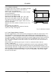
CV-A33CL 26 (1 .02 ) 8. External Appearance and Dimensions 4xM3 Depth 4 4M - 3深4 44 (1 .73 ) 5 (0 .2 ) 50 (1 .97 ) 7 .6 (0 .3 ) 58 (2 .28 ) DG I ITAL I /O 17 .5 (0 .69 ) 35 (1 .38 ) DC IN / TR IG U4-40 コネクター固定ネジ CM - oun t 50 (1 .97 ) 8 (0 .31 ) 26 (1 .02 ) 機銘版 (0 .2 ) 5 4xM3 4 6M -Depth 3深4 Fig. 26. Outline. 9. Specifications 9.1. Spectral sensitivity Fig. 27.
CV-A33CL 9.2.
CV-A33CL 10. Appendix 10.1. Precautions Personnel not trained in dealing with similar electronic devices should not service this camera. The camera contains components sensitive to electrostatic discharge. The handling of these devices should follow the requirements of electrostatic sensitive components. Do not attempt to disassemble this camera. Do not expose this camera to rain or moisture. Do not face this camera towards the sun, extreme bright light or light reflecting objects.
CV-A33CL 11. Users Record Camera type: CV-A33CL Revision: (Revision A) Serial No. …………….. Firmware version. …………….. Camera ID. …………….. Model name. …………….. User ID. …………….. For camera revision history, please contact your local JAI distributor. Users Mode Settings. Users Modifications. DECLARATION OF CONFORMITY AS DEFINED BY THE COUNCIL DIRECTIVE 89/336/EEC EMC (ELECTROMAGNETIC COMPABILITY) WE HEREWITH DECLARE THAT THIS PRODUCT COMPLIES WITH THE FOLOWING PROVISIONS APPLYING TO IT.