Industrial Monochrome CCD Camera CV-A50 / CV-A60 Operation Manual Camera: CV-A50 Revision B CV-A60 Revision A Manual: Version 2.1 A50Manualjul14.
CV-A50 / CV-A60 DECLARATION OF CONFORMITY AS DEFINED BY THE COUNCIL DIRECTIVE 89/336/EEC EMC (ELECTROMAGNETIC COMPABILITY) WE HEREWITH DECLARE THAT THIS PRODUCT COMPLIES WITH THE FOLOWING PROVISIONS APPLYING TO IT. EN-50081-1 EN-50082-1 Table of Contents 1. General......................................................................................................... 2 2. Standard Composition ....................................................................................... 2 3. Main Features ......
CV-A50 / CV-A60 1. General The difference from the previous manual is that the CCD sensor in CV-A50 is changed to new types. Now the used CCD sensors are: ICX-408AL-6, 409AL-6, 418ALL-6, 419ALL-6. The CV-A50/A60 is a range of monochrome CCIR and EIA interlaced 1/2” and 1/3” CCD cameras, designed for automated application, featuring an extremely small housing and a wide range of unique functions.
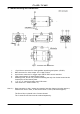
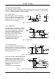
CV-A50 / CV-A60 4. Camera Housing and Dimensions Fig. 1. Locations and dimensions. 1. 2. 3. 4. 5. 6. 7. Note *1): 12 pin Hirose connector for frame grabber interfacing and power (12V DC). BNC connector for video output. VS 1.0 Vpp 75 Ohm. 6 pin Hirose connector for trigger input and RS-232C control interface. Gain potentiometer for manual gain setting. Mounting holes, 8 x M3. For precision mounting use only the 4 holes located at the forward part of the bottom plate.
CV-A50 / CV-A60 5. Pin Assignment 5.1. 12-pin Multi-connector (DC-IN/VIDEO OUT, EXT.HD/VD IN) Type: HR10A-10R-12PB-01 (Hirose) male Seen from rear. Pin configuration is compatible with EIAJ standard 9 1 2 8 10 11 3 7 12 4 5 6 Pin no. 1 2 3 4 5 6 7 8 9 10 11 12 Signal GND +12 V DC input GND Video output GND HD input/HD output VD input/VD output GND Pixel clock output WEN output Trigger input GND Remarks Parallel with the BNC connector. *) SW2.1 on for 75Ω. SW1.1 on for HD out. *) SW2.
CV-A50 / CV-A60 5.3. Input and Output Circuits In the following schematic diagrams the input and output circuits for video and timing signals are shown. Jumper settings are shown as for factory default. For alternative connections refer to “10.1. CV-A50/60 emulating CV-M50 interfacing.” 5.3.1. Video output The video output is a 75 Ω DC coupled circuit. The BNC connector and pin #4 on the 12-pin connector is in parallel. Avoid double termination. The video DC level is shown with 75 Ω termination.
CV-A50 / CV-A60 6. Functions and Operations Apart from the standard continuous operation, the CV-A50/60 features three external asynchronous trigger modes (edge pre-select, pulse width controlled and start/stop) and a special frame-delay readout mode. Long integration time mode is also supported. 6.1. Basic functions Some of the primary camera functions need a general introduction before the operation modes are described. The list below shows the primary functions from the command list.
CV-A50 / CV-A60 6.2. Input-output of HD/VD Signals In the default setting the camera will accept external HD/VD signals on pin 6 and 7 of the 12 pin Hirose connector. If external HD/VD is applied, the camera will synchronize to it. If no external sync signals are applied, the camera will operate with its internal x-tal controlled sync. The time requirements to the relation between VD and HD are shown in fig. 16. The input is TTL level as factory setting.
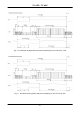
CV-A50 / CV-A60 Fig. 10. Horizontal timing details and pixel numbering for the CCD array. CCIR Fig. 11. Horizontal timing details and pixel numbering for the CCD array.
CV-A50 / CV-A60 Fig. 12. Vertical timing details for interlaced. CCIR Fig. 12A. Vertical timing details for non-interlaced.
CV-A50 / CV-A60 Fig. 13. Vertical timing details for interlaced. EIA Fig. 13A. Vertical timing details for non-interlaced.
CV-A50 / CV-A60 6.4. External Trigger Modes This camera has 5 external asynchronous trigger modes, which can be set by RS-232C commands. 1. 2. 3. 4. 5. Edge Pre-select Mode.TR=1 Pulse Width Control Mode. TR=2 Frame Delay read out mode. TR=3 Long Time Exposure Mode. TR=4 Start/stop Mode. TR=5 Pre-selected exposure. (SM=0, SM=1) Pulse width controlled exposure. PWC exposure read out by ext. VD. Exposure is interval between ext. VD. Exposure start by trigger and stop by ext.
CV-A50 / CV-A60 6.5. Edge Pre-select Mode The leading edge of the trigger pulse initiates the exposure. The exposure time (accumulation time) is governed by the pre-defined shutter speed set by RS-232C. The resulting video is output as “odd field” for EIA and “even field” for CCIR, and appear 9H (EIA9 or 10H (CCIR) after the leading edge of WEN (polarity is user selectable).
CV-A50 / CV-A60 6.6. Pulse Width Control Mode The leading edge of the trigger pulse initiates the exposure. The exposure time (accumulation time) is governed by duration of the trigger pulse. The resulting video is output as “odd field” for EIA and “even field” for CCIR, and appear 9H (EIA9 or 10H (CCIR) after the leading edge of WEN (polarity is user selectable). The exposure time range is 1.5H to 1000H (shortest and longest pulse duration).
CV-A50 / CV-A60 6.7. Frame-delay read out Mode This mode allows simultaneous capture of multiple camera using a common external trigger pulse subsequent multiplexed (sequential) readout using a single input frame grabber, as the user has control over when the image is read out from the CCD sensor. The exposure starts at the falling edge of the ext. trigger signal, and ends at the rising edge of the ext. trigger signal. (In the same way as Pulse Width Control mode).
CV-A50 / CV-A60 6.8. Long Time Exposure Mode The exposure time is the interval between 2 ext. VD pulses sent to the VD input of the camera (Pin No. 7 of the 12-pin Hirose connector). The exposure starts after input of the first ext. VD pulse, and ends after the next input of the next ext. VD pulse, which again starts a new exposure.
CV-A50 / CV-A60 6.9. Start/Stop Mode The exposure time is controlled by the interval between the ext. trigger and the ext. VD signal. The exposure starts at the first HD pulse after the falling edge of the ext. trigger, and stops 14.5 H after the falling edge of the VD pulse. It means that the trigger pulse must be applied after the external VD pulse, for exposures less than 14.5 H. The range can be between 1/60 to 1/10,000 for EIA, and 1/50 to 1/10,000 for CCIR.
CV-A50 / CV-A60 Important notes on using this mode:• As the start of exposure will be synchronized with the internal H signal, the start of exposure may be shifted by max 1H. • To avoid this shift (jitter), synchronize the camera with an external HD and make sure that the trigger pulse aligns to the HD signal as shown in Fig. 14. • For exposures <14 H, the trigger pulse is after the extern VD pulse. Fig. 26 6.10. Other Functions Gain and analogue settings.
CV-A50 / CV-A60 7. Configuring the Camera 7.1. RS-232C control. All configuration of the A50/60 camera is done via the RS-232C port. The camera can be set up from a PC running terminal emulator software, or using JAI´s camera control software. Below is the description of the ASCII based short command protocol. Communication setting.
CV-A50 / CV-A60 7.2. CV-A50/60 RS-232C command list. EB ST HP VN SC Command Name Format A – General settings and useful commands Echo Back EB=[Param.] Camera Status request ST? Online Help request HP? Firmware version VN? B – Timing and shutter related commands Scanning format SC=[Param.] TR Trigger mode TR=[Param.] SM SH Shutter mode Shutter speed SM=[Param.] SH=[Param.] PE Programmable expos. PE=[Param.
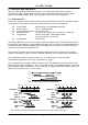
CV-A50 / CV-A60 7.3. Camera Control Tool for CV-A50/60 From www.jai.com CV-A50/60 Camera Control Tool for Windows 98/NT/2000 can be downloaded. The control tool contents a camera control program and tools for making your own program. Below the different windows are shown. Control bar Windows for all functions Fig. 28. Windows from Camera Tools. For the integrator and experienced user, the Camera Control Toll is much more than a program with a window interface.
CV-A50 / CV-A60 7.4. Internal Switch and Jumper Settings. 7.4.1 HD/VD input-output selection In the default setting the camera will accept external HD/VD signals on pins 6 and 7 of the 12 pin Hirose connector. The composite video signal from the camera will be synchronized to an external HD/VD source connected to the camera. TTL level (between 2 and 5 V). To set up the camera to output HD/VD signals on pins 6 and 7 on the Hirose connector follow these steps. See fig. 29. 1.
CV-A50 / CV-A60 8. Specifications Specifications Scanning system Frame rate (Full frame) Line frequency Pixel frequency CCD sensor 1/2”. CV-A50 *) CCD sensor 1/3”. CV-A60 Sensing area 1/2”. CV-A50 1/3”. CV-A60 Effective pixels Pixels in video output Cell size 1/2”. CV-A50 1/3”. CV-A60 Resolution horizontal Sensitivity CV-A50 (on sensor) CV-A60 S/N ratio CV-A50 CV-A60 Video output Gamma Gain Gain range Accumulation Synchronization Scanning HD sync.
CV-A50 / CV-A60 9. Spectral Sensitivity Relative Response 1.0 0.8 0.6 0.4 0.2 0.0 400 500 600 700 800 Wave Length (nm) 900 1000 Fig. 30. Spectral sensitivity. 10. Appendix 10.1. CV-A50 or CV-A60 emulating CV-M50 interfacing The CV-A50 and CV-A60 have a slightly different pin configuration on the 12-pin Hirose connector, compared to the M-series. This new configuration is compliant to the EIA-J standard.
CV-A50 / CV-A60 10.2. WEN out on pin 6 on 6 pin connector Instead of EEN output on pin #6 on the 6 pin Hirose connector, WEN can be output by jumper settings. The 2 jumpers are found on the main board PK8275B, if the bottom plate is removed. Signal on pin #6 EEN out WEN out JP1 open short JP2 short open Remark default Configuration shown in Bold+Italic is factory default setting JP1 JP2 Fig. 32. PK8275B main board 10.3. CV-A50/60 without sync on video output.
CV-A50 / CV-A60 10.4. Precautions Personnel not trained in dealing with similar electronic devices should not service this camera. The camera contains components sensitive to electrostatic discharge. The handling of these devices should follow the requirements of electrostatic sensitive components. Do not attempt to disassemble this camera. Do not expose this camera to rain or moisture. Do not face this camera towards the sun, extreme bright light or light reflecting objects.
CV-A50 / CV-A60 11. Users Record Camera type: CV-A50/60 CCIR/EIA Revision: CV-A60 Revision A. CV-A50 revision B Serial No. …………….. For camera revision history, please contact your local JAI distributor. Users Mode Settings: Users Modifications: Company and product names mentioned in this manual are trademarks or registered trademarks of their respective owners.