3CCD High Speed Color Line Scan Camera CV-L105 Operation Manual Camera: Revision A Manual: Version 1.1 CV-L105manJan9.
CV-L105 Table of Contents 1. General ........................................................................................................2 2. Standard Composition ......................................................................................2 3. Main Features ................................................................................................2 4. Locations and Functions ...................................................................................2 5. Pin Assignment.............
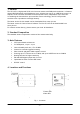
CV-L105 1. General The CV-L105 is a high-speed 3CCD color line scan camera with 2048 pixels resolution. It features digital LVDS RGB output with 30 MHz pixel rate, allowing line rate up to 14285 lines/second. An exposure control function facilitates constant exposure time, independent of the scan rate. In combining the latest dichroic prism and line sensor technology, the CV-L105 provides excellent color reproduction with high linearity. The latest version of this manual can be downloaded from: www.jai.
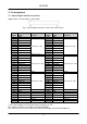
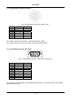
CV-L105 5. Pin Assignment 5.1. 68-pin Digital interface connector (Digital video, control signals, trigger input) Fig. 2. 68-pin digital interface. (Seen from camera rear.
CV-L105 5.2. 6-pin Hirose connector (Power) Fig. 3. 6-pin Hirose. (Seen from camera rear.) Pin no. 1 2 3 4 5 6 Signal NC NC GND GND NC +12V DC in Remarks Power GND Power GND + Power in The camera connector part number is Hirose H10A-7R-6P. (Male). The mating connector to use on the cable side is Hirose HR10A-7P-6S 5.3. 9-pin DSUB connector (RS-232C) 2 6 3 7 4 8 5 6 1 Fig. 4. 9-pin DSUB for RS-232C. (Seen from camera rear.) Pin no.
CV-L105 5.4. Input and Output Circuits Video outputs, timing outputs, trigger input and control inputs are found on the 68 pin LVDS connector. 5.4.1.
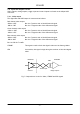
CV-L105 5.4.2. Trigger input The camera is triggered by an EIA-644 LVDS input signal pair. (+EXT TRIG in/ -EXT TRIG in (on pin #19 and pin #53)). Depending on the configuration of the camera, this input can provide operation in 4 modes: Internal Trigger. Scan mode. Internal Trigger. Shutter mode. External Trigger. Scan mode. External Trigger. Shutter mode. DS90C031 100 Twisted Image capture system DS90C032 Camera Fig. 6. Input receiver circuit for EXT TRIG 5.4.3.
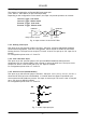
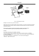
CV-L105 6. Functions and Operations 6.1. Principle of operation A line scan camera works according to the same principle as a fax machine, also sometimes referred to as a “push broom” operation. It captures a single line at a time (horizontal), and requires either the object or the camera to be moving to create the vertical direction of the image. Area Fig. 8. The principle of line scan.
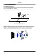
CV-L105 CV-L105 PC with Frame Horizontal Resolution Encoder Vertical Resolution Fig. 10. Specifying an encoder. Example of a camera set-up, with an encoder. When using a line scan camera together with an encoder, it is crucial to calculate the required specifications of the encoder in order to maintain the same aspect ratio in both vertical and horizontal resolution. The horizontal resolution is given by the number of pixels in the 3CCD camera.
CV-L105 6.2. Trigger modes Internal Trigger. Scan mode. The camera will operate continuously with its internal trigger. The exposure is equal to the scanning time set by the SCAN parameter via RS-232C only. SHUTTER parameter has no meaning here. SCAN value 150 µs through 32.5 ms. Internal Trigger. Shutter mode. The camera will operate continuously with its internal trigger. The scanning time is set by the SCAN parameter via RS-232C only. The exposure is set by the SHUTTER parameter via RS-232C only.
CV-L105 6.2.1. Internal Trigger. Scan mode. In this mode, the camera does not require an EXT TRIG signal to be issued to the camera. The line rate (scan rate) is generated inside the camera. The camera will operate continuously with its internal trigger. The exposure time is equal to the scanning time set by the SCAN parameter via RS-232C. The permitted range for the scan rate is 151 µs to 32.5 ms (corresponds to 6.6 kHz to 30 Hz). SHUTTER parameter has no function here.
CV-L105 6.2.2. Internal Trigger. Shutter mode. In this mode, the camera does not require an EXT TRIG signal to be issued to the camera. The line rate (scan rate) is generated inside the camera. The camera will operate continuously with its internal trigger. The scanning interval is equal to the time set by the SCAN parameter. The exposure time is equal to the Shutter time set by the SHUTTER parameter via RS-232C. The permitted range for the scan rate is 151 µs to 32.5 ms (corresponds to 6.6 kHz to 30 Hz).
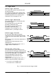
CV-L105 6.2.3. External Trigger. Scan mode. In this mode, the camera requires an EXT TRIG signal to be issued to the camera. The trigger signal is typical taken from an encoder. The exposure time is equal to the trigger interval. On the EXT TRIG input positive going edge the ongoing integration period is terminated and charge is read out. At the same time it starts a new cycle. The exposure time is therefore dependant of the line rate. SHUTTER and SCAN parameters has no function here.
CV-L105 6.2.4. External Trigger. Shutter mode. In this mode, the camera requires an EXT TRIG signal to be issued to the camera. The trigger signal is typical taken from an encoder. The scanning time is equal to the trigger interval. The exposure time is equal to the trigger low period (pulse width). For every EXT TRIG input negative going edge an integration period starts. It is terminated and charge is read out on the trigger positive going edge. The exposure time is therefore independant of the line rate.
CV-L105 6.3. Other functions 6.3.1. Binnig Binning is a function where the signal from two neighbour pixels are added and read out as a single pixel. The sensitivity will be double, but the resolution will be the half. The binning function has no influence on the internal scan rate and shutter setting. The function can be selected by RS-232C, internal jumper setting or on the I/F connector pin #10. For configuration please refer to 7.2 and 7.3. 6.3.2.
CV-L105 7. Configuring the Camera All configuration of the CV-L105 camera is done via the RS-232C port, which is factory setting. Binning and pixel rate settings can also be controlled by TTL signals into the interface connector or internal jumpers. From the factory, the camera will start up with the factory default. The factory setting is as follows: Clock 30 MHz Binning 2048 (Off) Trigger Internal Mode Scan Scan time 32.
CV-L105 Fig. 18. Shutter window 7.1.1. Clock Select With Clock Select two speeds can be selected, 15 MHz or 30 MHz. The 15 MHz operation will limit the maximum line rate (scan rate) to 7 172 Hz. It is recommended when a cable length of more than 20 metres is used or in applications where high RFI fields may be experienced. 7.1.2. Binning With Binning set to 2048 the full resolution of the CCD sensors is 2048 pixels.
CV-L105 7.1.6. Gain and offset adjustment Fig. 19. Gain and Offset window The individual gain and offset setting of each color is possible. This is required for adapting the white balance temperature for the 4 user configuration areas. For the factory default this setting has no function. It can only be adjusted with the internal potentiometers. The range of these settings is 0 – 255. 7.1.7.
CV-L105 7.2. Configuration via I/F connector and jumpers The binning function, pixel rate and RS-232C function can be controlled by TTL inputs on the 68pin Hirose interface connector and with jumper settings. Below table describe the possible states of these inputs. Please refer to fig. 7. for principle. RS-232C contr.
CV-L105 8. External Appearance and Dimensions Fig. 22.
CV-L105 9. Specifications 9.1. Specifications table Specifications Scanning system Pixel clock Line rate (scan rate) CCD sensor Sensing area Effective pixels Pixels in video output Cell size Prism block CCD alignment precision Sensitivity on sensor Radiometric at 3100K Sensitivity on sensor Photometric at 3100K S/N ratio CV-L105 Line scan 15 or 30 MHz, user selectable Up to 7172 lines/sec at 15 MHz, and up to 14285 lines/sec at 30 MHz 3 x 2048 line scan sensors mounted on an RGB prism 28.
CV-L105 10. Users Record Camera type: CV-L105 Revision: (Revision A) Serial No. …………….. Software version. …………….. For camera revision history, please contact your local JAI distributor. Users Mode Settings. Users Modifications. DECLARATION OF CONFORMITY AS DEFINED BY THE COUNCIL DIRECTIVE 89/336/EEC EMC (ELECTROMAGNETIC COMPABILITY) WE HEREWITH DECLARE THAT THIS PRODUCT COMPLIES WITH THE FOLOWING PROVISIONS APPLYING TO IT.