Digital Monochrome 2 Megapixel Progressive Scan Camera CV-M2 Operation Manual Camera: Revision A Manual: Version 1.0 M2ManualJul22.
CV-M2 Table of Contents 1. General ........................................................................................................2 2. Standard Composition ......................................................................................2 3. Main Features ................................................................................................2 4. Locations and Functions ...................................................................................3 5. Pin Assignment...............
CV-M2 1. General The CV-M2 is a digital 2 megapixel camera designed for automated imaging and ITS (Intelligent Traffic Systems) applications, featuring high resolution and high speed within a uniform and compact housing. The high-speed shutter function, asynchronous random trigger mode and partial scan mode allows the camera to capture high quality images of fast moving objects with a high frame rate.
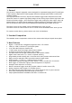
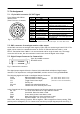
CV-M2 4. Locations and Functions 6 2 1 3 8 1. 2. 3. 4. 5. 6. 7. 8. CCD sensor Lens mount (C-mount) Rear panel with SW1 Digital output connector (Camera Link) DC in/Trigger in/RS-232C connector BNC connector for monitor video output Gain potentiometer Mounting holes M3. (8x) Fig. 1.
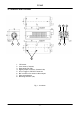
CV-M2 5. Pin Assignment 5.1. 12-pin Multi-connector (DC-IN/Trigger) Type: HR10A-10R-12PB-01 (Hirose) male. (Seen from rear of camera.) 9 1 2 8 10 11 3 4 7 12 5 6 Fig. 2. 12-pin connector. Pin no. 1 2 3 4 Signal GND +12 V DC input GND Iris Video output 5 6 7 8 9 10 GND RXD in TXD out GND EEN out Trigger/SG input 11 12 Factory use GND Remarks Analogue video for iris control in continuous mode and RCT mode. *) RS 232C. Or via Camera Link By internal switch HR/CL (Refer to 7.
CV-M2 5.4. Input and Output Circuits 5.4.1. Monitor video output On the BNC connector an analogue video signal for set-up is found if OS=2. The signal can be used for focus and field of view adjust. CCIR if MN=1. (50 fps, 17.734 kHz, 290 active lines.) EIA if MN=0. (60 fps, 17.734 kHz, 262 active lines.) It is for single channel normal (TR=0) operation only. Shutter speed <313 LVAL (CCIR). <263 LVAL (EIA). Video is composite 1Vpp from a 75 Ω source. 5.4.2.
CV-M2 5.4.5. Camera Link interface The video output is Camera Link, where the 2 channels with 10 or 8 bit video are placed in a base configuration. The digital output signals follow the Camera Link standardized multiplexed signal output interface. The output driver is NS type DS90CR285, and the receiver is NS type DS90CR286. The data bits from the digital video, FVAL, LVAL, DVAL and EEN are multiplexed into the twisted pairs, which are a part of the Camera Link.
CV-M2 6. Functions and Operations In the following the format shown in “7.5. CV-M2 command list” are used for function commands and parameters. 6.1. Basic functions The M2 camera is a progressive scan camera with 10 or 8 bit video output in single or dual channel Camera Link. On a BNC connector a standard composite video output CCIR or EIA for monitor use is found. The image covers the full format, but the resolution is much lower than the digital video output.
CV-M2 6.1.3. Restart continuous trigger mode The RCT mode makes it possible to use a lens with video controlled iris for intelligent traffic surveillance applications. TR=2. The camera is running continuously, and the iris is controlled from the iris video output. When a trigger pulse is applied, the scanning is reset and restarted, the previous signal is dumped with a fast dump read out, and the new triggered exposure is started. This fast dump read out has the same effect as “smearless read out”.
CV-M2 6.1.5. Sensor Gate Control This function is for applications where a strobe flash is the only illumination, and where the exact time for the strobe firing is not known. The time window for the strobe firing can be up to several frames. The resulting video read out can also be delayed by this function. It makes the synchronization of the frame grabber more flexible. The Sensor Gate Control signal will inhibit the internal SG signal so the accumulation can continue.
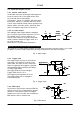
CV-M2 6.1.6. Digital video out allocation The set-up and the relations between the analog and digital video are shown in fig. 13. Digital video out [LSB] 1023 White clip level 890 100% level Analog video out 32 Black level 0 0 25 700 800 [mV] Fig. 13. Digital video bit allocation 6.1.7. Knee function. The knee functions can compress the signals in the highlighted areas. The slope over the knee point is only 20%. The Knee point can be adjusted from 712 to 1023.
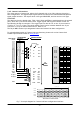
CV-M2 6.2. Sensor layout and timing. 6.2.1. CCD sensor layout The CCD sensor layout with respect to pixels and lines as it is used in the timing and video read out is shown below.
CV-M2 6.2.3. Horizontal timing single channel OS=0. Normal mode. Full frame. 1ck = 25 nsec 1 LVAL per i od 1916ck 1674ck LVAL 242ck FVAL Rai si ng Edge FVAL Fal l i ng Edge FVAL 52ck 1864ck SUB 444ck 190ck 514ck SG 958ck Exposur e Per i od mi n: 1. 5L( 1916+958ck) EEN 54ck OB Reser ved Reser ved OB Dummy+ 4ck 16ck Bl ank Ef f ect i ve Pi xel s 16ck 4ck 34ck 1600ck 276ck 242ck DATA OUT 34ck 316ck DVAL 6ck CCD Out 6ck 1600ck 1640ck 276ck Fig. 17.
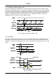
CV-M2 6.2.5. Horizontal timing dual channel OS=1. Normal mode. Full frame. 1ck = 25 nsec 1 LVAL per i od 1092ck 854ck LVAL 238ck FVAL Fal l i ng Edge FVAL Rai si ng Edge FVAL 52ck 1040ck SUB 186ck 32ck 514ck SG 546ck Exposur e Per i od mi n: 1. 5L( 1092+546ck) EEN 54ck 34ck OB Reser ved 16ck 4ck DATA OUT ( L ch) DATA OUT ( R ch) Dummy+ Bl ank Ef f ect i ve Pi xel s 800ck 272ck 238ck 292ck DVAL CCD Out ( L ch) CCD Out ( R ch) 34ck 6ck 6ck 800ck 820ck 272ck Fig. 19.
CV-M2 6.2.7. LVAL synchronous accumulation With LS=0, the accumulation will start synchronously with LVAL. The trigger pulse should be longer than 2 LVAL intervals, and the accumulation will then start at the first LVAL after the trigger leading edge. The exposure start delay will be up to 1 line. (Single channel 47.9 µsec. Dual 27.3 µsec). In EPS mode the exposure stops 0.5 L after the selected shutter time, (in number of LVAL). In PWC mode the exposure stops 0.
CV-M2 6.2.8. LVAL a-synchronous accumulation With LS=1, the accumulation will start immediately after the trigger leading edge. The exposure start delay will be 156 clk. pulses after the trigger. It is 3.9 µsec. In EPS mode the exposure stops 0.5 L after the selected shutter time, (in number of LVAL). In PWC mode the exposure stops 0.5 L after the trigger trailing edge. A new trigger must not be applied before the previous frame is read out. (FVAL is low).
CV-M2 6.2.9. Partial scanning vertical timing Partial scanning has 3 pre-selected vertical centred areas 1/2, 1/4 and 1/8. SC=1 through SC=3. With SC=3, the start and the height of the partial scanned area can be programmed with 1 line interval. The start line can be programmed with PS=1 through 1151. The scanned height can be programmed with PC=50 though 1200. Partial scanning will operate with single or dual channel output.
CV-M2 6.3. Input/Output of Timing Signals 6.3.1. Input of Timing Signals It is not possible to synchronize the camera from an external sync source except by an extern trigger pulse. The camera will always run with its internal X-tal controlled timing. Trigger input through Camera Link. TI=0 Trigger input as TTL on pin #10 on 12 pin Hirose. TI=1 The trigger polarity is active low. TP=0 Trigger input can be changed to active high. TP=1 6.3.2.
CV-M2 6.4.1. Continuous Operation (Non triggered) Mode settings can be done with RS-232C. Trigger Mode Normal. TR=0. It is for applications where the camera is continuously running without external trigger. The shutter mode can be normal or programmable exposure. (SM=0, SM=1). The shutter will work in all 10 steps up to 1/14,000 second or with the programmable exposure in 1216 steps. In partial scanning, shutter times longer than the actual frame time has no meaning.
CV-M2 6.4.2. Edge Pre-select Mode In EPS mode, the trigger leading edge will start an exposure at the first LVAL pulse if LS=0, (or immediately if LS=1), and it stops and the resulting image is read out after the pre-selected shutter time. It can be the 10 steps in normal or 1216 steps in programmable. SM=0 or SM=1. This mode will operate with full and partial scanning. An EEN pulse will indicate the active accumulation time, and a FVAL pulse indicates that the resulting video is read out.
CV-M2 6.4.3. Restart Continuous Trigger mode The RCT mode is in principle the same as normal continuous mode. The difference is that an external trigger pulse will immediately stop the video read out and reset and restart the vertical timing. After a fast dump read out, a new triggered exposure is started and read out as normal. The fast dump read out is performed with a speed 18 times faster for single output, and 10 times faster for dual output.
CV-M2 6.4.4. Pulse Width Control Mode In PWC mode, the trigger leading edge will start an exposure at the first LVAL pulse if LS=0 (or immediately if LS=1). It stops at the trailing edge of the trigger pulse, and the resulting video is read out. This mode will operate with full and partial scanning. An EEN pulse will indicate the active accumulation time, and a FVAL pulse indicates that the resulting video is read out. Long time exposure can be done with pulse width control mode.
CV-M2 6.4.5. Burst Trigger mode With the burst trigger function, a single trigger pulse can start a sequence with five previous set pre-selected programmable exposures. The five shutter times can be set with BSH1 through BSH5. (Exposure 1H through 1216H.) The exposure is LVAL synchronous. The sequence will start with the first exposure at the first LVAL pulse after the trigger leading edge, and the result is read out after the selected shutter time.
CV-M2 6.4.6. PIV mode. PIV mode (Particle Image Velocimetry) can be used in applications where 2 images should be taken with a very short time interval. It can only be used with strobe flash as illumination. The first accumulation time is fixed at 4 µsec. After a delay >1.5 µsec. the second exposure period starts. It is as long as the time for a full frame. The accumulation is LVAL a-synchronous. The first exposure period starts at the trigger leading edge.
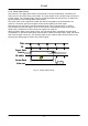
CV-M2 6.4.7. Sensor Gate Control This function is for applications with strobe flash illuminations or long time accumulations up to several frames. The resulting video is then read out after the first FVAL (or SG), following the trailing edge of the Sensor Gate Control signal. The sensor gate control signal can be synchronized by the FVAL signal. Fig. 29A. and fig. 29B. shows the minimum sensor gate signal width if it is synchronized to FVAL.
CV-M2 6.5. Other Functions. The following functions are described under their short ASCII command name. BA: Output bit allocation With this function the number of bits in the Camera Link video output can be selected to 10 or 8. If 8 bit is selected it is the 8 most significant bits. For the bit allocation in Camera Link output, please refer to “5.4.5. Camera Link interface” and to fig. 7.
CV-M2 7. Configuring the Camera 7.1. Mode setting SW1 on rear Switch SW 1.1 on the camera rear can be used to select digital or analogue video out. SW1.1 has higher priority than RS-232C. SW1.2 is for termination of the trigger 1 input on pin #10 Hirose. (SW1.3 is for termination of the factory test input on pin #11 Hirose) SW1.4 is for master gain selection. SW1.4 has higher priority than RS-232C. Fine gain adjustment on R channel by RS-232C. SW 1 Video out Trig 1 term.
CV-M2 7.4. RS-232C control All configuration of the CV-M2 camera is done via the RS-232C port on the 12 pin HR connector or via Camera Link. The control mode can be selected by the internal switch RS-232C/Camera Link. The camera can be set up from a PC running terminal emulator software, or using JAI´s camera control software. Below is the description of the ASCII based short command protocol. Communication setting.
CV-M2 7.5. CV-M2 command list EB ST HP VN ID MD UD OS Command Name Format A – General settings and useful commands Echo Back EB=[Param.] Camera Status request ST? Online Help request HP? Firmware version VN? Camera ID request ID? Model Name request MD? User ID UD=[Param.] B – Video Output Output select OS=[Param.] BA MN Output bit allocation BA=[Param.] Monitor mode MN=[Param.
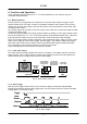
CV-M2 7.6. Camera Control Tool for CV-M2 From www.jai.com Camera Control Tool for Windows 98/NT/2000 can be downloaded. The control tool contents a camera control program and tools for making your own program. For the integrator and experienced user, the Camera Control Toll is much more than a program with a window interface. It also provides an easy and efficient ActiveX interface built for MS Windows 98, ME, NT and 2000.
CV-M2 8. External Appearance and Dimensions Fig. 38. Outline. 9. Specifications 9.1. Spectral sensitivity Relative response 1.0 0.8 0.6 0.4 0.2 0.0 300 400 500 600 700 Wave lenght (nm) 800 Fig. 39. Spectral sensitivity for M2.
CV-M2 9.2. Specification table Specifications Scanning system Pixel clock Line frequency, single output dual output Frame rate, single output dual output CCD sensor Sensing area Cell size Effective pixels Pixels in video output Full 1/2 partial 1/4 partial 1/8 partial Variable scan Sensitivity on sensor S/N ratio Video output digital single digital dual Monitor video output. Analogue Iris video output.
CV-M2 10. Appendix Precautions Personnel not trained in dealing with similar electronic devices should not service this camera. The camera contains components sensitive to electrostatic discharge. The handling of these devices should follow the requirements of electrostatic sensitive components. Do not attempt to disassemble this camera. Do not expose this camera to rain or moisture. Do not face this camera towards the sun, extreme bright light or light reflecting objects.
CV-M2 11. Users Record Camera type: CV-M2 Revision: (Revision A) Serial No. …………….. Firmware version. …………….. Camera ID. …………….. For camera revision history, please contact your local JAI distributor. Users Mode Settings. Users Modifications. DECLARATION OF CONFORMITY AS DEFINED BY THE COUNCIL DIRECTIVE 89/336/EEC EMC (ELECTROMAGNETIC COMPABILITY) WE HEREWITH DECLARE THAT THIS PRODUCT COMPLIES WITH THE FOLOWING PROVISIONS APPLYING TO IT.
CV-M2 - 34 -