Monochrome Double Speed Camera CV-M30 Operation Manual Camera: Revision D Manual: Version 1.0 CV-M30manDMay12.
CV-M30 Table of Contents 1. General ........................................................................................................2 2. Standard Composition ......................................................................................2 3. Main Features ................................................................................................2 4. Locations and Functions ...................................................................................3 5. Pin Assignment..............
CV-M30 1. General The CV-M30 camera revision D is an updated version with a new CCD sensor ICX-418ALL-6 with improved specifications. The revision D camera can only operate in double speed. CV-M30 is a monochrome CCD video camera designed for industrial video sensing applications. The camera operates with double speed scanning, where the horizontal and vertical frequencies is doubled compared to a standard camera. The image-capturing speed is the double.
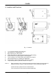
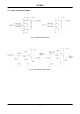
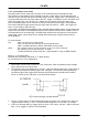
CV-M30 4. Locations and Functions Fig. 1. Locations 1. 2. 3. 4. 5. 6. 7. 8. 9. 1/2” interline-transfer type CCD sensor Lens mount for C-mount lenses. *1) BNC connector for video output Switch block SW1 for shutter speed and function mode setting 6-Pin connector for Input/output of control signals 12-Pin connector for 12V DC power and external sync signals Gain potentiometer for manual gain adjustment Screw holes for Tripod mount plate. (Screws 3.
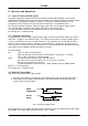
CV-M30 5. Pin Assignment 5.1. 12-pin Multi-connector (DC-IN/VIDEO OUT, EXT.HD/VD IN) Type: HR10A-10R-12PB-01 (Hirose) male Seen from rear. 9 1 2 8 10 11 3 4 7 12 5 6 Fig. 2. 12 pin connector Pin no 1 2 3 4 5 6 7 8 9 10 11 12 Signal GND +12 V DC input GND Video output GND HD input VD/trig input GND EEN output GND +12 V DC input GND Remarks Parallel with the BNC connector. *1) Parallel with pin 5 on 6 pin con. *2) Parallel with pin 2 on 6 pin con.
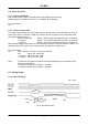
CV-M30 5.3. Input and Output Diagram Fig. 4. WEN and EEN output Fig. 5.
CV-M30 6. Functions and Operations 6.1. Input of External HD/VD Signals As factory setting the camera can be synchronized by external HD/VD signals. The external supplied HD/VD signal should follow the same standard as the camera setting for speed, scanning and interlace. The signal level must be 4.0 Vp-p ±2.0V with 75 Ohm termination on. The termination can be switched off with the internal switch SW1 on the PK8212 board.
CV-M30 6.3.1. Edge Pre-select Mode The edge pre-select mode will work in non-interlaced and field accumulation mode with partial scanning and double speed. The CV-M30 starts the exposure (= accumulation of photoelectric charge) at the first HD pulse after the falling edge of the ext. trigger pulse. The exposure ends after the time set by the 3 shutter switches SW1-1 to SW1-3. The accumulated signal will be read out as a single field before a new trigger can be applied.
CV-M30 6.3.2. Pulse Width Control Mode The pulse width control mode will only work in non-interlaced field accumulation mode. The exposure is controlled by the low period of the ext. trigger pulse. The CV-M30 starts the exposure at the first HD pulse after the falling edge of the ext. trigger pulse. The exposure ends at the first HD pulse after the rising edge of the ext. trigger. The Shutter can be controlled to be within the range from >1H (>32 usec.) to <1000H. The AC coupling causes the upper limit.
CV-M30 6.4. Other Functions 6.4.1. Double Speed Mode The CV-M30 camera revision D operates only with double speed scanning. Double speed is 120 fields per second. (V= 119.88Hz. H=31.468 kHz). To use this mode. Set: 6.4.2. Partial Scanning Mode To obtain a higher frame rate, the partial scanning can be used. In this mode only the vertical center part of the CCD sensor is read out. Partial scan will only work in non-interlaced mode.
CV-M30 6.5.2. External Sync Mode H = 31.778 µs Fig. 10. Vertical timing with external sync 6.5.3. External Sync Mode. Partial Scan H = 31.778 µs H = 31.778 µs Fig. 11.
CV-M30 6.5.4. Edge Pre-select H = 31.778 µs Fig. 12. Vertical timing for Edge pre-select 6.5.5. Edge Pre-select. Partial Scan H = 31.778 µs Fig. 13. Vertical timing for Edge pre-select 1/2 partial scanning H = 31.778 µs Fig. 14.
CV-M30 6.5.6. Pulse Width Control H = 31.778 µs Fig. 15. Vertical timing for pulse width control 6.5.7. Pulse Width. Partial Scan H = 31.778 µs Fig. 16. Vertical timing for pulse width control 1/2 partial scanning H = 31.778 µs Fig. 17.
CV-M30 7. Mode Setting 7.1. Switch SW1 on Rear Panel 7.1.1. SW1 Lay-out OFF SHUTTER SCAN mode 1 SCAN mode 2 TRIGGER GAIN ON 1 2 3 4 5 6 7 8 < < < < < < > > < > < > < > < < < > < > > > > > > < > > 2:1 Interlace Non-interlace Part. scan 1/2 N.I. Part. scan 1/3 N.I. SW 1 Off 1/200 1/500 1/1000 1/2000 1/4000 1/10,000 1/20,000 OFF = < ON = > < > < > Normal < > External MAN < > AGC Fig. 18. Switch settings for switch on rear 7.1.2. Table for SW1 Setting Switch no.
CV-M30 7.1.4. Scan Mode Settings With SW1-4 and SW1-6 the scanning mode can be selected. The table shows the modes. SW1-4 OFF ON OFF ON SW1-6 OFF OFF ON ON Function Mode 2:1 Interlaced mode 1/2 partial scan Non-interlaced mode 1/3 partial scan Remarks In Normal trigger mode only. (Continuous). Non-interlaced only Non-interlaced only For detail, please refer to “6.2. Continuous Operation.” and “6.4.2. Partial Scanning Mode.” 7.1.5. Double Speed Mode Vertical frequency 119.88Hz, and horizontal 31.468kHz.
CV-M30 7.2. Internal Switch and Jumper Settings Inside the camera there are switches for 75 termination of external trigger/VD and HD and for trigger mode select. There are also jumpers for gamma select. 7.2.1. Trigger/VD and HD Termination On the PK8212 board switch SW1 for 75 Ohm termination of external trigger/VD and HD is found. SW1-1 is for external HD termination. SW1-2 is for external trigger or external VD termination. ON is 75 Ohm termination. It is factory setting. OFF is for TTL level. 7.2.2.
CV-M30 8. Internal Adjustments of Video Signal For adjustment of the video output signal there are internal potentiometers on th PK 7987A board. Adjustment should only be done in a setup with a standard test chart and controlled illumination Do not touch these potentiometers unless you are familiar with camera adjustments. VR 1 is for AGC level setting. Factory setting is 700 mVpp ±30 mV VR2 is for black level set-up. Factory setting is 20 mVpp ±2 mV VR3 is for white clip level.
CV-M30 9. External Appearance and Dimensions Fig. 22.
CV-M30 10. Specifications 10.1. Specification table Model CCD Sensor Image Area Effective Pixels Cell Size Pixels in video output Double Speed 2:1 interlaced Non-interlaced 1/2 partial 1/3 partial Vertical Frequency Horizontal Frequency Pixel Clock Frequency Pixel clocks per line Synchronization CV-M30 1/2”Monochrome IT CCD. Sony ICX-418ALL-6 6.45mm (H) x 4.84mm (V) 768(H) x 494(V) 8.4 µ m(H) x 9.
CV-M30 11. Appendix 11.1. Precautions Personnel not trained in dealing with similar electronic devices should not service this camera. The camera contains components sensitive to electrostatic discharge. The handling of these devices should follow the requirements of electrostatic sensitive components. Do not attempt to disassemble this camera. Do not expose this camera to rain or moisture. Do not face this camera towards the sun, extreme bright light or light reflecting objects.
CV-M30 12. Users Record Camera type: CV-M30 Revision: (Revision D) Serial No. …………….. For camera revision history, please contact your local JAI distributor. Users Mode Settings. Users Modifications. DECLARATION OF CONFORMITY AS DEFINED BY THE COUNCIL DIRECTIVE 89/336/EEC EMC (ELECTROMAGNETIC COMPABILITY) WE HEREWITH DECLARE THAT THIS PRODUCT COMPLIES WITH THE FOLOWING PROVISIONS APPLYING TO IT.