Double Speed Progressive Scan CCD Camera CV-M40 Operation Manual (Rev.
CV-M40 DECLARATION OF CONFORMITY AS DEFINED BY THE COUNCIL DIRECTIVE 89/336/EEC EMC (ELECTROMAGNETIC COMPATIBILITY) WE HEREWITH DECLARE THAT THIS PRODUCT COMPLIES WITH THE FOLLOWING PROVISIONS APPLYING TO IT.
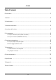
CV-M40 Table of Contents CE declaration ............................................................................................................................. 2 1. General .................................................................................................................................... 4 2. Main features .......................................................................................................................... 4 3. Standard composition .........................
CV-M40 1. General The CV-M40 is a 1/2” CCD progressive scan camera, incorporating double speed and partial scan techniques, housed in a compact and robust package. Using the latest CCD sensor technology with square pixels provides excellent resolution and signal to noise ratio, together with flexible asynchronous random trigger functions and multitude of user settings. 2. Main Features 1/2" IT monochrome CCD sensor 654 (h) x 494 (v) x 9.
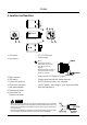
CV-M40 4. Locations and functions 9 1 8 2 1. CCD sensor 2. Lens mount : : 3 4 5 7 6 1/2 “ IT CCD sensor C-mount type Note : Rear protrusion on Cmount lens must be less than 10 mm (0.4 inch approx). When IR-cut filter is used, it must be less than 7.0 mm (0.28 inch approx). 3. 4. 5. 6. 7. 8. 9. BNC connector SW1 switch 6 pin multi connector 12 pin multi connector Gain potentiometer Tripod mount plate Screw holes for Tripod mount plate : : : : : Video output (VS 1.
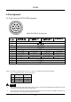
CV-M40 5. Pin assignment 5-1. 12 pin connector (DC IN/SYNC connector) HR10A-10R-12PB-01 (Hirose) male Pin No. Ext Sync Mode Ext Trigger Mode Ext Trigger Mode (Factory setting) H-Reset H Non-reset 1 GND 2 DC+12V IN 3 GND(VIDEO) 4 VIDEO OUT 5 GND Int Sync Mode 6 Ext.HD IN Ext.TRIG IN Ext.HD IN Int.HD OUT 7 Ext.VD IN WEN OUT Ext.TRIG IN Int.VD OUT PLCK/WEN OUT NC 8 GND 9 NC PLCK/WEN OUT 10 GND 11 DC+12C IN 12 GND * Note : To change the signal output on pin no.
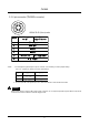
CV-M40 5-2. 6 pin connector (TRIGGER connector) HR10A-7R-6P (Hirose) male HD/VD input or output Pin no. 1 TXD output 2 RXD input 3 Ground 4 Ground 5* **See note 2. 6* * Note : Ext. trigger/readout Ext. trigger input WEN output 1. To change the signal output on pin no. 5 and 6, it is necessary to make jumper setting. See “7-2. Jumpers on board” for more informations. Pin no. Factory pre-set Others 5 Trigger input NC 6 WEN output NC 2. Do not input HD or VD signal at pin no.
CV-M40 6. Functions and operations 6-1. Input/output of HD/VD signal a) Input of external HD/VD signal (Factory pre-set) To input ext. HD/VD signal, make JP9/JP11 short-circuited, and JP12/JP13 open-circuited. To change the termination of ext. HD/VD signal, it is neccessary to make the jumper JP8/JP10 short-circuited. All jumpers are located on PK8273 board. For details, please refer to 7-23. Jumpers on PK8273 board. Note : Factory pre-set is set at HD/VD input (TTL) .
CV-M40 a) Set SW1-5 at ON, and SW1-6 at OFF to select the Edge pre-select mode. b) Set SW1-1 to SW1-3 to select the appropriate shutter speed. For controlling the shutter speed by the RS 232C serial interface, set SW1-8 at ON. c) Set the SW1-4 switch to ON to select the Binning mode and set the switch SW1-7 to OFF to select the Partial scan mode. CAUTION The pulse width of the external trigger pulse must be 2H to 1300H. 6-2-2.
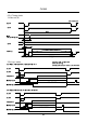
CV-M40 6-2-4. Timing charts 1. Video out (H) Note:1ck=40.7nsec Ext.HD Int.HD 780ck WEN (Positive/Negative) 3.78 s 20ns Int.VD 700ns 100ns Video out Valid period 18ck 60ck 2.Ext. sync mode Note 1:Sync or HD is not mentioned Note 2:1H=31.777 2-a) Normal readout(1/60sec.1frm=525H,60frm/sec.) Ext.VD 1H 9H 15H 492H WEN(positive) 1H 18H 8H 7H WEN(Negative) 2-b) Binning readout(1/120sec.1frm=262H,120frm/sec.) Ext.HD Ext.VD 8.
CV-M40 2-c) Partial Scan Ext.VD 1H Int.VD 1H 9H 9H Video out WEN (Positive) Valid period B A 1H C 7H WEN (Negative) Effective readout line A B C 240 line 44H 240H 11H 120 line 65H 120H 15H 60 line 79H 60H 17H 30 line 86H 30H 18H Note 1:Sync or HD is not mentioned Note 2:1H=31.777 S Note 3:WEN polarity can be chosen at JP22 of I/F board 3.Edge pre-select mode Note 1:Sync or HD is not mentioned 3-a) 60 fps = normal readout Note 2:1H=31.
CV-M40 Enlarged Note : The following charts discribes the delay of the exposure TRIG XSUB sec. 1.4 ~ 1.5 Exposure time 3-c) partial scan Ext.Trig 0.032mS 40mS VIDEO OUT WEN(positive) Valid period B A 1H Exposure time C 7H WEN(Negative) Effective readout line A B C 240 line 45H 240H 13H 120 line 66H 120H 17H 60 line 80H 60H 19H 30 line 87H 30H 20H Note 1:Sync or HD is not mentioned Note 2:1H=31.
CV-M40 4.Pulse width control mode 4-a) 60 fps = normal readout Ext.Trig not re-set at HD sync 0.064mS 40mS 1H VIDEO OUT WEN(positive) Note 1:Sync or HD is not mentioned Note 2:1H=31.777 S Note 3:WEN polarity can be chosen at JP22 of I/F board 494H Valid period 14H 1H Exposure time WEN(Negative) 7H 7H Waiting for Ext.Trigger 4-b) 120 fps = binning readout not re-set at HD sync Ext.Trig 0.
CV-M40 Unit : 1HD (31.777 µsec.) 5.Frame-delay readout mode Note 1:Sync or HD is not mentioned Note 2:1H=31.777 S Note 3:WEN polarity can be chosen at JP22 of I/F board 5-a) 60 fps = normal readout not re-set at HD sync Ext.Trig 0.1mS 40mS Trigger pulse (longer than exposure time) 1H 2H VIDEO OUT WEN(positive) 494H Valid period 13H Exposure time 1H V.transfer are freezed WEN(Negative) 6H 7H Waiting for Ext.Trigger 5-b) 120 fps = binning readout not re-set at HD sync 0.1mS 40mS Ext.
CV-M40 7. Mode setting 7-1. SW1 switch on the rear panel OFF ON SW no. Switch function Setting mode OFF ON 1 Shutter speed 2 Refer to "6-1-1.Shutter speed" 3 4 Binning mode 5 6 Ext. trigger/readout mode 7 Partial scan mode OFF ON 8 RS 232C interface OFF ON OFF ON Refer to "6-1-3. Ext. trigger/readout mode" Note : The above switches are set at OFF position by factory pre-set. 7-1-1.
CV-M40 7-1-2. Binning mode (SW1-4) This switch selects the Binning mode. OFF ON : Normal mode (60 frames/sec.) : Binning mode (120 frames/sec.) CAUTION At the Binning mode, please note that vertical resolution would be lower (1/2 approx.) of normal mode. 7-1-3. Ext. trigger/readout modes (SW1-5, SW1-6) These switches select the ext. trigger/readout mode, as below. Switch setting (OFF : /ON : ) Ext. trigger mode SW1-5 SW1-6 OFF Edge pre-select Pulse width control Frame-delay readout 7-1-4.
CV-M40 7-2. Jumpers on board 7-2-1. Jumpers on PK8201 board Jumpers JP1 and JP2 are used to select the gamma setting. See table below for options. Please note that both jumpers must be in the “open” position to allow RS 232C setting of gamma. If no setting is provided via RS 232C, the camera will default to gamma 1.0. JP2 Setting by jumpers Jumpers Setting Forbidden by 0.45 1.
CV-M40 7-2-3. Jumpers on PK8273 board a) Jumpers JP8 thru JP13 control the input/output state as well as the termination of the HD and VD signals on pin #6 and #7 of the 12 pin connector. Function Mode Int. Sync Ext. Sync H Reset Trigger (12P) H Non Rest Trigger (12P) H Reset trigger (6P) H Non Reset trigger (6P) Pin no.
CV-M40 c) JP22 WEN Polarity Reversing When JP22 is set to OPEN, WEN is output, and only 1H period becomes HIGH level before video output starts. The periods from WEN output and video start may differ at each mode. When JP22 is set to SHORT, WEN’s image output period becomes LOW level, and after finishing output, it becomes HIGH level. The periods from WEN output and video start is same at each mode.
CV-M40 8.
CV-M40 9. Specification Model name CV-M40 Scanning system CCD sensor 525 lines, 60 frames/sec. Monochorme 1/2" IT CCD sensor progressive scan Sensing area for video out 6.4 mm (h) x 4.8 mm (v) Effective pixels 659 (h) x 494 (v) 9.9 (h) x 9.9 (v) µm Cell size Resolution (horizontal) 480 TV line Resolution (vertical) 480 TV line Sensitivity 0.23 Lux, Max gain, 50% video S/N ratio 48 dB (AGC OFF, Gamma=1.0) Video output Composite VS signal 1.0Vpp at 75Ohm or Video without sync. 0.
CV-M40 10. Appendix 10.1. Precautions Personnel not trained in dealing with similar electronic devices should not service this camera. The camera contains components sensitive to electrostatic discharge. The handling of these devices should follow the requirements of electrostatic sensitive components. Do not attempt to disassemble this camera. Do not expose this camera to rain or moisture. Do not face this camera towards the sun, extreme bright light or light reflecting objects.
CV-M40 11. User’s Record Camera type: CV-M40 Scanning system: EIA Revision: (Revision C) Serial No. ................. Users Mode Settings Users Modifications This manual can be downloaded from: www.jai.
2700-11114 E C1 0701 JAI A·S, Denmark Produktionsvej 1, 2600 Glostrup Copenhagen, Denmark Phone +45 4457 8888 Fax +45 4491 8880 www.jai.com JAI Corporation, Japan German Industry Center 1-18-2 Hakusan, Midori-ku Yokohama, Kanagawa 226-0006, Japan Phone +81 45 933 5400 Fax +81 45 931 6142 www.jai-corp.co.jp JAI America, Inc., USA Suite 450 23046 Avenida de la Carlota Laguna Hills, CA 92653 USA Phone +1 949 472 5900 Fax +1 949 472 5908 www.jai.