Digital Monochrome and Color Megapixel Progressive Scan Cameras + + CV-M4 /M4 CL + + CV-M7 /M7 CL Operation Manual Camera: Revision B Manual: Version 1.0 Preliminary M4plusBman1may07.
CV-M4+/M4+CL, CV-M7+/M7+CL Table of contents 1. General ........................................................................................................2 2. Standard Composition ......................................................................................2 3. Main Features ................................................................................................2 4. Locations and Functions ...................................................................................3 5.
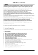
CV-M4+/M4+CL, CV-M7+/M7+CL 1. General This manual will cover the following 4 cameras: CV-M4+/CV-M4+CL and CV-M7+/CV-M7+CL. The revision B cameras are updated with a new function, Restart Continuous Trigger mode (RCT). The trigger can be H a-synchronous or H synchronous. Binning is now only vertical. The cameras are based on progressive scan 2/3” CCD megapixel interline transfer sensors. CV-M4+ is a digital monochrome progressive scan CCD camera with LVDS output.
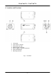
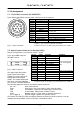
CV-M4+/M4+CL, CV-M7+/M7+CL 4. Locations and Functions 1. 2. 3. 4. 5. 6. 7. CCD sensor Lens mount (C-mount) Rear panel with SW1 Digital output connector DC in/Trigger in/RS-232C connector Gain potentiometer Mounting holes M3 Fig. 1.
CV-M4+/M4+CL, CV-M7+/M7+CL 5. Pin Assignment 5.1. 12-pin Multi-connector (DC-IN/RS232C) Type: HR10A-10R-12PB-01 (Hirose) male. (Seen from rear of Pin no. Signal 1 GND 2 +12 V DC input 9 1 3 GND 2 8 10 4 Video output 5 GND 3 11 12 7 6 RXD in 4 6 5 7 TXD out 8 GND 9 EEN/sync out 10 Trigger input 11 Multi shutter 12 GND camera.) Remarks Analogue video for test and iris control *) Or via Camera Link for CL+ versions if JP 301 short *1) composite sync. *2) Or on LVDS or Camera Link.
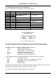
CV-M4+/M4+CL, CV-M7+/M7+CL 5.3. Digital Output Connector for Camera Link This pin configuration is only valid for CV-M4+CL and CV-M+7CL Pin no.
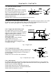
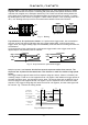
CV-M4+/M4+CL, CV-M7+/M7+CL 5.4. Input and Output Circuits Video Output L 5.4.1. Video output 75 1µ2 The analogue video output without composite sync is a 75 Ω DC coupled circuit. It is for test 68p only. It can be used for iris control if the NC camera is in normal mode. The video black level is 0.5 volt without termination. The video is without composite sync. Analogue video in partial scan is only valid for the scanned area.
CV-M4+/M4+CL, CV-M7+/M7+CL 5.4.5. Camera Link interface For Camera Link the digital output signals follow the Camera Link standardized multiplexed signal output interface. The output driver is NS type DS90CR283, and the receiver is NS type DS90CR284. The data bits from the 10 bit digital video, FEN, LEN. EEN and DVAL are multiplexed into the twisted pairs, which are a part of the Camera Link. Trigger signals and the serial camera control is feed directly through its own pair.
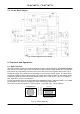
CV-M4+/M4+CL, CV-M7+/M7+CL 5.5. CV-M4+ Block Diagram Fig. 9. Block diagram for the camera 6. Functions and Operations 6.1. Basic functions The CCD scanning format can be selected between full or partial scanning. With partial scanning only the vertical central part of the CCD sensor is read out with a higher frame rate. The partial scan is done by a fast dump read out of the lines in the vertical ccd register down to the top of the partial image.
CV-M4+/M4+CL, CV-M7+/M7+CL Binning mode is a function where the signal charge from 2 or more adjacent pixels are added together and read out as one pixel. A resulting full frame with lower spatial resolution can be read out with a higher rate, and higher sensitivity. The CV-M4+ has vertical binning where the pixel charge from 2 adjacent lines are added together in the horizontal ccd register. It is done by double pulses to the vertical ccd register. Lowest shutter speed is 1/50. In binning mode H is 43.
CV-M4+/M4+CL, CV-M7+/M7+CL Color versions CV-M7+ and CV-M7+CL These color cameras are identical to the monochrome cameras. Only the CCD sensor is changed to a RGB primary color type. Here the color mosaic lay out is shown in fig. 13. left. This lay out is known as a Bayer filter. Based on the knowledge to this mosaic, a full RGB signal can be constructed by some calculations in the host Pc as shown in the following example.
CV-M4+/M4+CL, CV-M7+/M7+CL Restart Continuous Trigger mode. RCT. The RCT mode makes it possible to use a lens with video controlled iris for intelligent traffic surveillance applications, ITS. The camera is running continuously, and the iris is controlled from the iris video output. When a trigger pulse is applied, the scanning is reset, the previous signal is dumped with a fast dump read out, and the new triggered exposure is started. This fast dump read out takes 133 H (5,23 msec.
CV-M4+/M4+CL, CV-M7+/M7+CL 6.3. Continuous Operation (Non triggered) Mode settings can be done with either RS-232C or switches. Trigger Mode Normal. TR=0. It is for applications where the camera is continuous running without external trigger. The shutter mode can be normal or programmable exposure. (SM=0, SM=1). The shutter will work in all 10 steps up to 1/10,000 second or with the programmable exposure in 1056 steps.
CV-M4+/M4+CL, CV-M7+/M7+CL Fig. 17. Vertical timing details, full frame. Fig. 17A. Vertical timing details with vertical binning (M4+ and M4+CL only).
CV-M4+/M4+CL, CV-M7+/M7+CL Fig. 18. Vertical timing details with 1/2 partial scanning. Fig. 18A. Vertical timing details with 1/4 partial scanning. Fig. 18B. Vertical timing details with 1/8 partial scanning. Table showing timing figures for continuous modes Scanning mode Lines/ frame Lines in video out Pixels/ line Pixels/line in video out H time µs Rate fps Pix clk MHz Full 1060 1030 1592 1380 39.32 24 40.49 V binning 565 515 1752 1380 43.27 44 40.
CV-M4+/M4+CL, CV-M7+/M7+CL 6.4. External Trigger Modes This camera has 3 external asynchronous trigger modes, which can be set by RS-232C commands or switches. 1. 2. 3. Edge Pre-select Mode. TR=1 Pulse Width Control Mode. TR=2 Frame Delay read out mode. TR=3 Pre-selected exposure. (SM=0, SM=1) Pulse width controlled exposure. Pre-select exp. Read out by trailing trig. edge. The trigger can be H synchronous (HC=0) or H a-synchronous (HC=1). Refer to fig. 12.
CV-M4+/M4+CL, CV-M7+/M7+CL 6.5. Edge Pre-select Mode The trigger leading edge will start the exposure H synchronous or H a-synchronous (HC=0, HC=1). The exposure stops and is read out after the shutter time selected. It can be the 10 steps in normal or 1056 steps in programmable. SM=0 or SM=1. This mode will operate with full and partial scanning and with V-binning (M4+ and M4CL+ only). Partial scanning and binning in combinations is not allowed.
CV-M4+/M4+CL, CV-M7+/M7+CL Remark that the dump read out in smearless takes 133H before the accumulation start. Fig. 20A. Edge Pre-select, smearless Fig. 21. Edge Pre-select with Restart Continous Trigger.
CV-M4+/M4+CL, CV-M7+/M7+CL 6.6. Pulse Width Control Mode In this mode the exposure starts from the leading edge of the trigger pulse, H synchronous or H a-synchronous. It stops at the trailing edge of the trigger pulse, and the resulting video is read out. This mode will operate with full and partial scanning and with all binning modes (M4+ and M4+CL only). Partial scanning and binning in combinations is not allowed. The pulse width control mode can be used for long time integration.
CV-M4+/M4+CL, CV-M7+/M7+CL 6.7. Frame-delay read out Mode In this mode the pre selected exposure starts from the leading edge of the trigger pulse, H synchronous or H a-synchronous. It can be the 10 steps in normal or 1056 steps in programmable. SM=0 or SM=1. The resulting video is read out at the trailing edge of the trigger. This mode will operate with full and partial scanning and with V binning (M4+ and M4+CL only). Partial scanning and binning in combinations is not allowed.
CV-M4+/M4+CL, CV-M7+/M7+CL 6.8. Frame-delay read out Mode with multiple exposure. Multiple exposures is possible in frame delay read out mode. The pre selected exposure starts from the leading edge of the trigger pulse. It can be the 10 steps in normal or 1056 steps in programmable. SM=0 or SM=1. The resulting video is read out at the trailing edge of the trigger. This mode will operate with full and partial scanning and with binning (M4+ and M4+CL only).
CV-M4+/M4+CL, CV-M7+/M7+CL 6.9. Other Functions. Functions which can be controlled by either RS-232C or switches, or both. Gain and set-up. !! Do not adjust these settings unless you have knowledge to video adjustments!! The video gain is set to manual. In manual gain mode, either the gain level (GA) or the rear potentiometer (RP). can adjust the level. Set-up level. (SU). This setting can adjust the set-up level (or black level). Vertical Binning (BI). Only vertical binning is possible.
CV-M4+/M4+CL, CV-M7+/M7+CL 7. Configuring the Camera CONTROL > < < < > < > < > < > < > < < < > > > < > < < < > > > < > Norm al < > Sm ear-less Local < > RS232C 1/8 part. 1/4 part. Pulse width Edge pre sel. seconds < < > > > < > > < Frame delay 1/10,000 < > < 1/5000 1/1500 < < < > > < 1/2 part. SMEAR-LESS 1/800 SCANNING < < < < < > Off EXT. TRIGGER < < < Full SHUTTER 1/200 2 3 4 5 6 7 8 9 10 1/400 ON 1 1/50 1/100 OFF 1/24 Rear SW 1/3000 7.1.
CV-M4+/M4+CL, CV-M7+/M7+CL 7.4. RS-232C control All configuration of the CV-M4+ camera is done via the RS-232C port. On the 12 pin Hirose connector, if JP301 is open, or via Camera Link if JP301 is short. The camera can be set up from a PC running terminal emulator software, or using JAI´s camera control software. Below is the description of the ASCII based short command protocol. Communication setting.
CV-M4+/M4+CL, CV-M7+/M7+CL 7.5. CV-M4+ command list EB ST HP VN SC Command Name Format A – General settings and useful commands Echo Back EB=[Param.] Camera Status request ST? Online Help request HP? Firmware version VN? B – Timing and shutter related commands Scanning format SC=[Param.] Parameter 0=Echo off Remarks 1=Echo on Off at power up Actual setting Command list 3 letter version TR Trigger mode TR=[Param.
CV-M4+/M4+CL, CV-M7+/M7+CL 7.6. Camera Control Tool for CV-M4+ From www.jai.com Camera Control Tool for Windows 98/NT/2000 can be downloaded. The control tool contents a camera control program and tools for making your own program. Below the different windows are shown. Fig. 28. Camera control tool windows.
CV-M4+/M4+CL, CV-M7+/M7+CL 8. External Appearance and Dimensions Fig. 29. Outline 9. Specifications 9.1. Spectral sensitivity 1.0 0 .8 0.8 Relative response Relative response 1.0 0.6 0.4 0.2 0.0 400 500 600 700 800 Wave lenght (nm) 900 1000 B G R IR st op 0 .6 0 .4 0 .2 0 .0 400 50 0 600 70 0 800 Wave len gt h (n m ) Fig. 30. Spectral sensitivity for M4+/M4+CL Fig. 31.
CV-M4+/M4+CL, CV-M7+/M7+CL 9.2. Specification table Specifications Scanning system Pixel clock Line frequency Line freq. with V binnig Frame rate for full frame Frame rate for V binning CCD sensor Sensing area Cell size Effective pixels Pixels in video output Full V binning 1/2 partial 1/4 partial 1/8 partial Sensitivity on sensor S/N ratio Video A/D conversion Video output digital Video output analogue Gamma Gain Gain range Synchronization Sync.
CV-M4+/M4+CL, CV-M7+/M7+CL 10. Appendix 10.1. Precautions Personnel not trained in dealing with similar electronic devices should not service this camera. The camera contains components sensitive to electrostatic discharge. The handling of these devices should follow the requirements of electrostatic sensitive components. Do not attempt to disassemble this camera. Do not expose this camera to rain or moisture. Do not face this camera towards the sun, extreme bright light or light reflecting objects.
CV-M4+/M4+CL, CV-M7+/M7+CL 10.3. Camera Link Test points Inside the camera Link versions cameras CV-M4+CL and CV-M7+CL there are some useful test points, which can be a big help in system troubleshooting. The timing signals are multiplexed into the Camera Link, so it is not possible to use an oscilloscope to control the timing for a camera frame grabber system.
CV-M4+/M4+CL, CV-M7+/M7+CL 11. Users Record Camera type: CV-M4+ M4+CL M7+ M7+CL Revision: (Revision B) Serial No. …………….. Software version. …………….. For camera revision history, please contact your local JAI distributor. Users Mode Settings. Users Modifications. DECLARATION OF CONFORMITY AS DEFINED BY THE COUNCIL DIRECTIVE 89/336/EEC EMC (ELECTROMAGNETIC COMPABILITY) WE HEREWITH DECLARE THAT THIS PRODUCT COMPLIES WITH THE FOLOWING PROVISIONS APPLYING TO IT.