CV-M77 Progressive Scan Camera CV-M77 Operation Manual Camera: Revision A Manual: Version 1.
CV-M77 -2-
CV-M77 1 2 3 4 5 General...................................................................................................................... 5 Standard Composition............................................................................................. 5 Main Features ........................................................................................................... 5 Camera Housing and Dimensions .......................................................................... 6 Pin Assignment ...
CV-M77 12.2.4 Patterned Noise .............................................................................................................. 27 12.3 References......................................................................................................................... 27 13 14 Users Record.......................................................................................................... 28 Index.............................................................................................
CV-M77 1 General The CV-M77 camera is a compact RGB color progressive scan camera designed for automated imaging applications. The 1/3" CCD sensor with square pixels and primary mosaic filter offers a superb image quality and the build in DSP assures high color reproduction. The camera incorporates several triggered modes and various shutter functions to capture moving objects and to control the light.
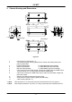
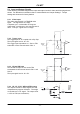
CV-M77 26 (1.02) 4 Camera Housing and Dimensions 5 (0.2) 50 (1.97) 4-M3 depth5 50 (19.7) 90 (3.54) 7.6 (0.3) 53 6 7 RS-232C TRIG DC IN R 40 (1.57) 4 MG B SW1 RGB/ SYNC 1 (C-Mount) 2 (CCD chip) 4-M3 depth5 50 (19.7) 8 26 (1.02) 5 (0.2) 11 Figure 4-1 1 2 3 4 5 6 7 8 9 10 11 *1) Note: *2) Note: Lens mount of C-mount type. *1) 1/3" interline transfer CCD progressive scan sensor with square pixels and primary mosaic filter R Gain Potentiometer. To adjust Red gain level manually.
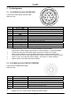
CV-M77 5 Pin Assignment 5.1 12-pin Multi-connector (DC-IN/SYNC.) 9 1 Type: HR10A-10R-12PB-01 (Hirose male) Seen from rear. 2 8 10 11 3 7 12 4 6 5 Pin No. 5.1.1.1 Signal 5.1.1.2 Remarks 5.1.1.3 GND 1 +12V DC input 2 GND 3 NC 4 GND 5 SW-S301.1 “ON” for 75Ω termination, SW-S303.1 “OFF” for HD output Ext.HD input 6* SW-S301.2 “ON” for 75Ω termination, SW-S303.2 “OFF” for VD output Ext.VD input 7* GND 8 PCLK out: JP305 “short”, JP306 “open” NC 9* NC: JP309 and JP310 “open”.
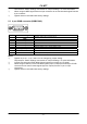
CV-M77 *) *) 5.3 See section 8 “Switch Settings” and section 9 “Jumper Settings ” for more information. When using the WEN signal from the 6 pin connector do not use the same signal from the 9 pin connector. Signals shown in bold italics are factory settings. 9-pin DSUB-connector (RGB/SYNC.) Pin No. 1* 2 3 4* 5 6* 7* 8 9* 5.3.1.1 Signal NC GND R output G output B output HD input Sync output GND NC 5.3.1.2 Remarks VD input: JP303 “open” and JP304 “short” Sync. on G: SW302-3 “ON” HDinput: SW303-1 “ON”.
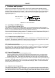
CV-M77 5.4 Input and Output Circuits In the following schematic diagrams the input and output circuits for video and timing signals are shown. For alternative connections refer to “Internal Switch and Jumper Settings”. Jumper settings are shown as for factory default. 5.4.1 Video input The video output signal is a 75Ω RGB video signal. The signal level is 0.7Vpp. Composite sync. is selectable on the green video signal via software or the internal switch 302-3. The sync. signal level is 0.3Vpp.
CV-M77 6 Functions and Operation Apart from the standard continuous operation, the CV-M77 features three external triggering modes, Edge Pre-select, Pulse Width Control mode and Readout Delay mode. These 3 external triggering modes operate with H non-reset. In H non-reset, the exposure will be synchronized to the internal HD and the exposure will start at the first HD after the negative going edge of the trigger (see figure 6-1). EDGE PRE-SELECT H non-reset Trigger int.
CV-M77 time (accumulation time) is governed by the fixed shutter speed set up by the rear panel DIPswitches or via RS-232C control. The resulting video signal will start to be read out after the selected shutter time. The WEN pulse indicates the start of valid video signal. Refer to timing charts for details. A new trigger pulse must not be applied before the video read out has finished. If the camera is synchronized to an external HD signal, there are some requirements to the phase between the ext.
CV-M77 Set SW1-5 and SW1-6 on the rear plate of the camera to “ON” and SW1-7 to OFF or use the RS 232C control to set-up the PWC mode of the camera. 6.3.3 Frame-delay Readout Mode This trigger mode operates in H non-reset mode. In H non-reset mode the trigger and HD is synchronized. The exposure will start at the first HD pulse after the falling edge of the external trigger signal. The exposure ends at the rising edge of the external trigger signal. The trigger pulse must be longer than >1H.
CV-M77 6.4 Timing diagram for Horizontal and Vertical Sync.
CV-M77 6.5 Timing diagram for Edge Pre-select mode TRIG 1H=50.8µs 2H Min 2H Min EXT HD INT HD INT VD 1.5H-2.5H 9H 1.5H-2.5H EEN Exposure time Exposure time 0.5H 0.5H WEN 17H 4H 4H Video out 770H Effective video 6.6 Timing diagram for Pulse Width Control mode 1H=50.8µs TRIG 1H Min 1H-2000H EXT HD INT HD INT VD 9H 0.5H-1.5H 0.5H-1.5H EEN Exposure time WEN 0.5H Exposure period 0.5H 17H 4H 4H Video out 770H Effective video 6.
CV-M77 6.8 Timing diagram for Long Time Exposure mode 1H=50.8µs EXT HD INT VD EXT VD INT VD 1V x N (2VD Min) 1H Max 1H Max 9H EEN WEN Exposure time 17H 4H 4H Video out 770H Remarks: 1VD indicates 792H. The interval of EXT VD input has to be multiple number of 1VD.
CV-M77 7 Configuring the camera using the serial interface. 7.1 Mode Setting using ASCII commands via the RS-232C port. The configuration of the CV-M77 camera can be done via the RS-232C port. The camera is to be set up via an ASCII terminal or from a PC running terminal emulator software. Below is the description of the ASCII based short command protocol. The RS-232C serial interface specification for CV-M77 is: 7.2 Communication setting Baud Rate Data Length Stop Bit Parity Xon/Xoff Control 7.
CV-M77 C - Gain and analogue signals settings. AS=[Param.] 1 AGC switch AS? GA=[Param.] 2 Master gain level GA? RG=[Param.] 3 Red gain level RG? BG=[Param.] 4 Blue gain level BG? AG=[Param.] 5 AGC level AG? 6 White balance WB=[Param.] WB? 7 Auto white balance AW=[Param.] SU=[Param.] 8 Master setup level SU? RS=[Param.] 9 Red setup level RS? BS=[Param.
CV-M77 Response to firmware version request command Example: Request Command (PC→Camera) Command Name Format Version Request 7.4 Receiving Data(Camera→PC) Remarks *** *** is Version No.
CV-M77 8 Switch Settings Before changing any switch settings or jumper settings turn off the power. 8.1 Mode Settings by Switch The factory setting for the SW-1 switch on the rear panel of the camera is OFF: The electronic shutter is OFF, the external trigger modes are OFF, gamma is OFF (=1.0), the AGC is OFF and the RS-232C control is disabled.
CV-M77 The SW301 switches (1-3) in “ON” position activates 75Ω termination of ext.HD and ext.VD signals and it activates 75Ω termination of an ext.trigger signal. The factory setting is “OFF” enabling TTL signal termination for all three signals. 8.2.2 SW302 switch S302 OFF ON White - 1 xxxx Balance 2 xxxx Sync. on G: 3 xxxx WEN: 4 xxxx The SW302 switch has the following functions: The switches (1-2) determines the color temperature, the switch (3) activates Composite sync.
CV-M77 9 Jumper settings Before changing any switch settings or jumper settings turn off the power. 9.1 Jumper locations The jumpers are located on two boards, the PK8309A board and the PK8308A board: JP402 JP401 1SS302 D1FS4 02CZ7.
Jumper table Function JP301 Ext. HD input Int. HD output Ext. VD input Ext.
CV-M77 10 CV-M77 Camera Control Tool The Camera Control Tool software for the CV-M77 camera is available from the JAI homepage (www.jai.com). The software runs under Windows 98, NT and Windows 2000. The software interface has incorporated all the commands described in the ASCII protocol in an easy to use fashion – more user-friendly for some than the HyperTerminal or similar programs. From www.jai.com Camera Control Tool software for windows 98/NT/2000 can be downloaded.
CV-M77 Fig. Windows from the Camera Control Tools software.
CV-M77 11 Specifications Scanning system Pixel clock Line frequency Frame rate CCD sensor Sensing area Effective pixels Pixels in video output Cell size Sensitivity on sensor S/N ratio Video output Progressive 792 lines 24.8 frames/sec. 25.000 MHz 19.685 kHz (1270 pixel clock/line) 24.8 frames/sec. (792 lines/frame) 1/3” RGB primary color IT CCD 4.8 (h) x 3.6 (v) mm 1034 (h) x 779 (v) 1028 (h) x 770 (v) 4.65 (h) x 4.65 (v) µm 1.5 Lux (Max. gain, 50% video) >50 dB RGB video signal, 0.
CV-M77 11.1 Spectral sensitivity 1. 0 Relative response 0 .8 G B R IR s t o p 0 .6 0 .4 0 .2 0 .
CV-M77 12 Appendix 12.1 Precautions Personnel not trained in dealing with similar electronic devices should not service this camera. The camera contains components sensitive to electrostatic discharge. The handling of these devices should follow the requirements of electrostatic sensitive components. Do not attempt to disassemble this camera. Do not expose this camera to rain or moisture. Do not face this camera towards the sun, extreme bright light or light reflecting objects.
CV-M77 13 Users Record Camera type: CV-M77 Revision: (Revision A) Serial No. …………….. Users Mode Settings Users Modifications 14 Index No index.