3 CCD RGB Color Camera CV-M91 Operation Manual Camera: Revision A Manual: Version 1.1 M91Manualjan19.
CV-M91 Table of Contents 1. General............................................................................................... 2 2. Standard Composition ............................................................................. 2 3. Main Features ....................................................................................... 2 4. Locations and Functions ........................................................................... 3 5. Pin Assignment ............................................
CV-M91 1. General The CV-M91 3 CCD RGB color camera is a new updated version of CV-M90. The prism is improved, and new CCD sensors are used. The new CCD sensor has 5 dB higher sensitivity, 15 dB lower smear and 4 dB higher dynamic range. Now there are Y/C output and input for composite sync. Pulse width control shutter is now fully implemented.
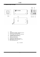
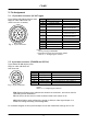
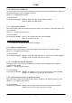
CV-M91 4. Locations and Functions 11 1. 2. 3. 4. 5. 6. 7. 8. 9. 10. Prism Lens mount (C-mount). Thread max 4 mm Switch SW1 for mode settings 6 pin Trigger input and RS-232C connector 12 pin DC in/Sync connector 9 pin Sub-D connector for video Red gain potentiometer Blue gain potentiometer Switch for one push white balance Mounting hole 1/4” for tripod. ¼ - 20 11. M3 mounting holes 4x Fig. 1.
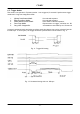
CV-M91 5. Pin Assignment 5.1. 12-pin Multi-connector (DC-IN/Trigger) Type: HR10A-10R-12PB-01(Hirose) male. Plugs for cable: HR10A-10P-12S (Seen from rear of camera.) 9 1 2 8 10 11 3 4 7 12 5 6 Fig. 2. 12-pin connector. Pin no. Signal 1 GND 2 +12 V DC input 3 N/C 4 NC/VBS video out Remarks *), VBS 75 Ω source SW604-1 on for VBS out 5 6 GND HD in/HD out 7 VS in/VD in/VD out 8 9 10 11 12 GND NC/Pixel clock out *), 75 Ω source GND +12 V DC input GND 75 Ω term.
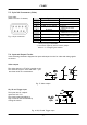
CV-M91 5.3. 9-pin Sub D-connector (Video) Type: male. (Seen from rear of camera.) Fig. 4. 9-pin connector. Pin no. 1 2 3 4 Signal GND GND R output G out or G+S output 5 6 B output Y video out or VBS out 7 Sync out or WEN out 8 9N GND C video out Remarks 75 Ω source. 75 Ω source. *) , SW604-4 off for G out 75 Ω source 75 Ω source. *), SW604-2 off –3 on for Y out 75 Ω source *), JP303 o JP304 c for Sync out 75 Ω source Notes: Factory setting in bold italic.
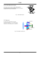
CV-M91 HD, VD, WEN, EEN and PCLK output 10k The output circuit for HD, VD, WEN, EEN and PCLK are complementary emitter followers with 75 Ω in series. Output level is 4V. (Non-terminated). TTL 220 10 67 10 GND 10k Fig. 7. HD and VD output. 5.5. Prism unit Blue CCD For best color performance, the lens should be designed for 1/3” 3CCD camera. Otherwise color shading can be a problem. Green CCD Red CCD Fig. 9. Principle for prism unit.
CV-M91 6. Functions and Operations The different camera modes and functions can be set by switches and jumpers. Some functions like RGB setup and white clip can only be changed via RS-232C. Function names within “ “ are names used in camera control tool. 6.1. Input/Output of Signals 6.1.1. Input/output of HD/VD In the default setting the camera will accept external HD/VD signals on pin 6 and 7 of the 12 pin Hirose connector. If external HD/VD is applied, the camera will synchronize to it.
CV-M91 6.1.2. Internal sync out/WEN out On pin #7 on 9 pin sub-D connector, the factory setting is the internal composite sync signal out. By jumper settings it can be changed to WEN out. Refer to “7. Configuring the Camera.” To use this mode: Set function on PK8407: JP303 o, JP304 s for sync output. Factory default. JP303 s, JP304 o for WEN output. 6.1.3. Internal pixel clock out The internal pixel clock can be output on pin #9 on the 12 pin connector. As factory setting it is not connected. Refer to “7.
CV-M91 6.2. Trigger Modes This camera can operate in 5 primary modes. 1 non-triggered, 3 external H synchronous trigger modes and 1 long time integration mode. 1. 2. 3. 4. 5. Normal continuous Mode. Edge Pre-select Mode. Pulse Width Control Mode. Start Stop Mode Long time integration Pre-selected exposure. Pre-selected exposure. Pulse width controlled exposure. Exposure start on trigger, end after ext. VD Accumulation controlled by ext.
CV-M91 6.2.1. Continuous Operation (Non triggered) Trigger Mode Normal. It is for applications where the camera is continuous running without external trigger. The shutter will work in all 8 steps up to 1/10,000 second. Refer to “7. Configuring the Camera.” To use this mode: Set function: Trigger mode “Normal”. SW1-4 to OFF On PK8407: JP301 open, JP302 open, JP331 short. Factory setting. Accumulation to “Frame” or “Field”. SW 301-4 to ON or OFF Scanning to “Interlaced” or “Non-Interlaced”.
CV-M91 Fig. 15. Vertical timing PAL interlaced Fig. 16. Vertical timing PAL non-interlaced.
CV-M91 Fig. 17. Vertical timing NTSC interlaced Fig. 18. Vertical timing NTSC non- interlaced.
CV-M91 6.2.2. Edge Pre-select Mode The exposure will start at the first HD after the trigger leading edge, and it stops after the selected shutter time, and the resulting video is read out. An EEN pulse indicate the accumulation time, and a WEN pulse that the resulting video read out. Refer to “7. Configuring the Camera.” To use this mode: Set function: Input: Trigger mode to “Edge pre-select”. SW 1-4 to ON On PK8407: JP301 open, JP302 open, JP331 short. Factory setting. Accumulation to “Field”.
CV-M91 6.2.3. Pulse Width Control Mode The exposure will start at the first HD after the trigger leading edge, and it stops between the first and second HD after the trigger trailing edge. An EEN pulse indicate the accumulation time, and a WEN pulse indicates that the resulting video is read out. Refer to “7. Configuring the Camera.” To use this mode: Set function: Input: Trigger mode to “Pulse width control”. SW 1-4 to ON On PK8407: JP301 open, JP302 open, JP311 open. Accumulation to “Field”.
CV-M91 6.2.4. Start Stop Mode The exposure time is controlled by the interval between the ext. trigger and the ext. VD signal. The exposure starts at the first HD pulse after the falling edge of the ext. trigger, and stops 14.5 H after the falling edge of the VD pulse. It means that the trigger pulse must be applied after the external VD pulse, for exposures less than 14.5 H. The range can be between 1/77 to 1/10,000. The Start/Stop mode is a continuous mode where the VD signal must be given continuously.
CV-M91 6.2.5. Long time integration The exposure time is the interval between 2 ext. VD pulses sent to the VD input. (Pin No. 7 of the 12-pin connector). The exposure starts after input of the first ext. VD pulse, and ends after the next input of the next ext. VD pulse, which again starts a new exposure. The long time exposure is a continuous process where each external VD will synchronize the camera, stop the exposure, start a new exposure and read out the previous accumulated signal.
CV-M91 6.3. Other Functions. Refer to “7. Configuring the Camera.” Scanning: SW1-5 on rear selects interlaced or non-interlaced. Non-interlaced PAL = 312H in EVEN field. Non-interlaced NTSC = 262 H in ODD field. Gamma: SW1-6 on rear for gamma select. Gamma = 1 or gamma =0.45. Gain: SW1-7 on rear select manual gain or AGC. Manual gain is set by VR7 on PK8406. In AGC the gain is automatic. The AGC level is set by potentiometer VR3. Control: SW1-8 on rear selects the camera control mode.
CV-M91 7. Configuring the Camera 7.1 Switch settings The switch positions are shown in factory setting. Names in bold italic is factory setting. OFF SHUTTER TRIGGER INTERLACE GAMMA GAIN CONTROL ON 1 2 3 4 5 6 7 8 second SW 1 on rear 1/60 1/125 1/250 1/500 1/1000 1/2000 1/4000 1/10,000 7.1.1. SW1 on rear panel Note: SW1-1 through 3 OFF: In Normal mode: The shutter is OFF In Trigger mode: 1/50 for PAL. 1/60 for NTSC < < < < > > > > < < > > < < > > < > < > < > < > Normal Intel. Gam. 1 Man.
CV-M91 7.2. Jumper settings inside Factory settings is shown in bold italic HD/VD input output on pin #6 and Jumper HD/VD in HD/VD out JP305 short open JP306 open short JP308 short open JP309 open short #7 on 12 pin connector. Remarks VD input/output. HD input/output. HD/VD input on pin #6 and #7 or composite VS signal in on pin #7. Jumper HD/VD in VS in Remarks JP312 short open JP313 open short Instead of HD and VD input on pin #6 and pin #7 a composite signal VS can be input on pin #7.
CV-M91 7.3. Switch and jumper positions 1. 2. 3. 4. PK8407 PK8404 PK8406 PK8408 Rear Front 1 4 2 3 Fig. 35. Board positions. JP310 JP311 JP315 JP318 JP319 JP302 JP309 JP305 JP 306 SW 301 SW 301 for 75Ω term. JP 301 JP 313 JP 312 JP 304 JP 303 JP 308 Fig. 36. Jumpers and switches on PK8407. SW 201 Off <-> ON SW 202 Off <-> ON SW 201 for CCD iris SW 604 SW 202 for White bal. SW 604 for Video output Fig. 37. Switches on PK8404. Fig. 38. Switches on PK8408.
CV-M91 7.3. RS-232C control The CV-M91 camera functions can be set up via the RS-232C port on the 6 pin HR connector. The JAI camera control tool for CV-M91 can be used for it. To use this mode: Set function: Control. SW1-8 on rear to ON. RS-232C. (Switch setting before power on). Other functions Important notes on using this mode. • Communication setting.
CV-M91 7.5. Camera Control Tool for CV-M91 From www.jai.com Camera Control Tool for Windows 98/NT/2000 can be downloaded. The control tool contains a camera control program and tools for making your own program. For the integrator and experienced user, the Camera Control Tool is much more than a program with a window interface. It also provides an easy and efficient ActiveX interface built for MS Windows 98, ME, NT and 2000.
CV-M91 8. External Appearance and Dimensions Important notes. • C-mount thread on lens should be less than 4.0 mm. • Use only lenses designed for 1/3” 3 CCD cameras. Fig. 41. Outline. 9. Specifications 9.1. Spectral sensitivity The resulting relative response for the prism and the CCD sensor characteristics combined. 1.0 Relative response 0.8 G B R 0.6 0.4 0.2 0.0 400 500 600 700 800 Wave length (nm) Fig. 42.
CV-M91 9.2. Specification table Specifications Scanning system Frame rate Line frequency Pixel frequency CCD sensors Sensing area Effective pixels Pixels in video output Cell size Resolution horizontal Sensitivity (on sensor) S/N ratio Video outputs.
CV-M91 9.3. CV-M91 Opto-mechanical specifications Fig. 43. Opto mechanical specifications.
CV-M91 10. Appendix 10.1. Precautions Personnel not trained in dealing with similar electronic devices should not service this camera. The camera contains components sensitive to electrostatic discharge. The handling of these devices should follow the requirements of electrostatic sensitive components. Do not attempt to disassemble this camera. Do not expose this camera to rain or moisture. Do not face this camera towards the sun, extreme bright light or light reflecting objects.
CV-M91 11. Users Record Camera type: CV-M91 Revision: (Revision A) Serial No. …………….. For camera revision history, please contact your local JAI distributor. Users Mode Settings. Users Modifications. DECLARATION OF CONFORMITY AS DEFINED BY THE COUNCIL DIRECTIVE 89/336/EEC EMC (ELECTROMAGNETIC COMPABILITY) WE HEREWITH DECLARE THAT THIS PRODUCT COMPLIES WITH THE FOLOWING PROVISIONS APPLYING TO IT.