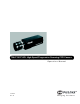
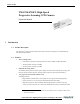
TM-6710/6710CL High-Speed Progressive Scanning CCD Camera Operation Manual 69-0058 Rev.
i Notice Page Notice The material contained in this manual consists of information that is proprietary to JAI PULNiX, Inc., and may only be used by the purchasers of the product. JAI PULNiX, Inc. makes no warranty for the use of its product and assumes no responsibility for any errors which may appear or for damages resulting from the use of the information contained herein. JAI PULNiX, Inc. reserves the right to make changes without notice.
ii Table of Contents 1 Introduction . . . . . . . . . . . . . . . . . . . . . . . . . . . . . . . . . . . . 1 1.1 1.2 1.3 1.4 Product Description . . . . . . . . . . . . . . . . . . . . . . . . . . . . . . . . . . Features. . . . . . . . . . . . . . . . . . . . . . . . . . . . . . . . . . . . . . . . . . . . Applications . . . . . . . . . . . . . . . . . . . . . . . . . . . . . . . . . . . . . . . . System Configuration. . . . . . . . . . . . . . . . . . . . . . . . . . . . . . . . .
iii List of Figures FIGURE 1. TM-6710 System Configuration . . . . . . . . . . . . . . . . . . . . . . . . . . . . . . . . . . 3 FIGURE 2. TM-6710CL System Configuration. . . . . . . . . . . . . . . . . . . . . . . . . . . . . . . . 4 FIGURE 3. 51-Pin Connector . . . . . . . . . . . . . . . . . . . . . . . . . . . . . . . . . . . . . . . . . . . . . 7 FIGURE 4. Camera Link Connector. . . . . . . . . . . . . . . . . . . . . . . . . . . . . . . . . . . . . . . . . 7 FIGURE 5.
August 30, 2004 TM-6710/6710CL High-Speed Progressive Scanning CCD Camera Operation Manual 1 Introduction 1.1 Product Description The TM-6710* is a high-resolution monochrome CCD camera with “quad speed” 120FPS dual-tap, dual-channel digital output. 1.
Page 2 Introduction - Progressive scan, which eliminates interlace deterioration of the image while offering an easy-to-use computer interface. - High sensitivity and low noise at fast scanning. Can drive faster than 25 MHz pixel clock rate. Excellent S/N ratio (>45 dB, 8-bit typical). Built-in micro lens. - Partial scan capability, which allows 100 and 200 lines of partial scan up to 300Hz scanning. • Asynchronous reset The TM-6710 captures an image using asynchronous reset.
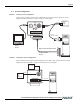
Page 3 Introduction 1.4 System Configuration FIGURE 1. TM-6710 System Configuration Figure 1 below presents a typical system configuration for the TM-6710 camera. Please see “Power Supply and Power Cable Setup” on page 7 for info on power supplies. Ext. Sync Power Trigger Analog video SHUTTER B 9 3 4 56 CD E 01 2 A UP VIDEO 4 5 6 2 3 78 0 1 78 9 POWER DWN MODE DIGITAL RS-232 P/N: CS-232-B912 Multi Sync Analog Monitor Digital cable: P/N 50DG-02LP Frame Grabber Board FIGURE 2.
Page 4 Installation 2 Installation The following instructions are provided to help you to set up your video camera system quickly and easily. We suggest that you read through these instructions prior to unpacking and setting up your camera system. 2.1 Getting Started 2.1.1 Unpacking Instructions We recommend that you save the original packing cartons for the cameras in case you need to return or exchange an item.
Page 5 Installation 2.2 Camera Setup 2.2.1 Pin Configurations 2.2.1 (a) 12-Pin Connector (TM-6710) The TM-6710 has a 12-pin connector for power input. Pin #1 is Ground and Pin #2 is +12V DC. The other pins handle a number of other input and output functions, as detailed below. Pin 1 2 3 4 5 6 2.2.
Page 6 Installation 2.2.1 (c) 51-Pin Connector The TM-6710 has a 51-pin connector for RS-644 digital output (using B channel digital output to configure single channel). FIGURE 3. 51-Pin Connector 18 1 35 19 51 2.2.1 (d) 36 Pin# Description Pin# Description Pin# Description 1 A0+ 18 CLK+ 35 CLK- 2 B0+ 19 A0- 36 GND 3 A1+ 20 B0- 37 VCC (jumper) 4 B1+ 21 A1- 38 VCC (jumper) 5 A2+ 22 B1- 39 EXT.
Page 7 Installation FIGURE 5. MDR 26-Pin Connector (0226-622VC) MDR 26-Pin Connector (0226-622VC) 2.2.
Page 8 Installation If you are building your own power cables, consult the pin-out for the camera purchased. Connect the Ground and +12V power leads of the PC-12P power connector to Pin #1 and Pin #2, respectively. Remember that power must be DC regulated, and of sufficient current to properly power the camera. Attach the power cable to the connector. The 12-pin connector is keyed and will only fit in one orientation. Rotate the connector while applying slight pressure until the keyways line up.
Page 9 Installation D-Sub 9-Pin Connector (ITEM 15-1007) PIN 1 PIN 2 TO COMPUTER COM PORT PIN 3 To pin #12 of 12-pin female connector To pin #10 of 12-pin female connector PIN 4 PIN 5 To pin #5 of 12-pin female connector PIN 6 PIN 7 PIN 8 PIN 9 2.2.4 Attaching the Video Output (Analog Output on TM-6710 Only) Connect a BNC cable to the output from the camera and the input to your system (frame grabber analog input). The input of the system or monitor should be balanced for 75ohms termination.
Page 10 Operation Operation 3.1 Dual-Tap Video Output The TM-6710CL uses a dual-tap output for its fast frame readout. At the same horizontal clock cycle, line 1 and all odd lines go to channel A, and line 2 and all even lines go to channel B. Vertical shift registers move twice per horizontal blanking period. Lines are grouped in twos, so that 1 and 2, and 3 and 4, and so on, are output from channel A and B simultaneously.
Page 11 Operation FIGURE 9.
Page 12 Operation 3.2.1 Mode Mode Control Switches (TM-6710) Control Switch Up/Down Switch 0 Normal mode 1 Gain control (A/B) up - increase gain of Ch. A down - decrease gain of Ch. A 2 Gain (A/B) fine tune up - increase gain of Ch. A down - decrease gain of Ch. A, while decrease/increase gain of Ch. B, at 5:1 ration 3 Main Vref control up - increase gain of Ch. A down -decrease A/D voltage reference of Ch. A & Ch. B 4 Vref balance control up - increase gain of Ch.
Page 13 Operation 3.3.2 External Synchronization The TM-6710 can take external HD and VD for phase locking. The internal PLL will take external HD and lock with the CCD HD. (The CCD HD frequency is half of the analog video output HD.) Example: Ext. HD = 30.49KHz, VD will be 120Hz and Master Clock will be 50.98MHz. INSIDE CAMERA OUTSIDE CAMERA 1µF Ext HD (or Ext VD) C1 4.7k R1 External Sync Input Schematic The internal sync generator will take external VD to generate internal VD.
Page 14 Operation • Internal Fast Reset Mode • Internal Slow Reset Mode Mode 0: Async Mode 1-4: Async Mode: 5-8: Async Mode 9: 3.3.3 (a) Normal Mode Fast Mode Slow Mode External pulse width control mode External Pulse Width Control Mode The TM-6710 can be reset with external reset pulse (VINIT). Set the dial switch to “9.” Apply a pulsewidth control VINIT signal generated from an external 100Ω (VINIT) event trigger to the camera.
Page 15 Operation This feature is especially important in capturing moving objects at the precise location of the field of view, such as belt conveyer, fast event observation and still picture capturing. 3.3.3 (b) Internal Fast Reset Mode The video signal has no delay from the reset timing. Shutter speed range is 1/8,000 to 1/31,000 sec. Select a dial switch setting from “1” to “4.
Page 16 Operation FIGURE 12. Internal Slow Reset Mode Pulse (VINIT) min 2H Hd 1 2 3 4 5 6 7 8 9 10 Internal Vinit External X 5H Transfer Gate Pulse 7H Discharge pulse Exposure Time Composite Video 3.3.4 Partial Scan Mode A key advantage of the TM-6710 is the partial scan mode, which provides up to 300Hz frame rate output. 200 line partial scan is output at 236Hz. 100 line partial scan is output at 300Hz.
Page 17 Operation 3.3.6 Progressive Scanning The TM-6710 uses a state-of-the-art CCD called a “Progressive scanning interline transfer CCD” which scans all lines sequentially from top to bottom at one frame rate 120 Hz or (60 Hz) with dual channel output. Like a non-interlace computer screen, it generates a stable crisp image without alternating lines and provides full vertical TV resolution of 484 active lines. The interline transfer architecture is also important to generate simultaneous shuttering.
Page 18 Operation 3.3.7 (b) RS-232C Control Commands External RS-232C (or optional RS-485) computer control allows the operator to remotely adjust the following functions: clock speed, shutter, gain, A/D reference and scan format. The control commands are detailed below. Note: RS-232 control will override the rear panel switch control. (TM-6710 only) The TM-6710 command package begins with “.” (Start of Text = 3AH), and is then followed by the Command Code (C.C...
Page 19 Operation This selects a mode for external shutter speed control. Hexadecimal shutter number (3 digit) follows “SX” command (e.g., “080” = 128H, shutter speed = 4.1msec). It moves the shutter discharge pulse at every 1H (32 µsec.) period from 254 (no shutter) to 1H (max. speed). Command G Function: A/D pre-amp gain control. The “GM” command controls the gains of the A channel and the B channel. The “GA” and “GB” commands fine tune the gain of the A and B channels respectively, to achieve balance.
Page 20 Operation Vref2) is between 1V and 0.2V. The controllable range of the reference top voltage (Vtop) is between 1.5V and 3V. Vtop Voltage V 4 3 3 Vtop 2.15V 2 2 1K (10-bit) 256 (8-bit) A/D Input 1 1 Vbtm 0.45V 0 0 Figure 1 Examples: Counts 255 Figure 2 Vref (V) “:”, “VT”, “7E”, CR 7EH = Vref top: 126 3AH, 56H, 37H, 45H, 36H, 0DH 1.2 1 0.8 0.6 0.4 Command W 0.2 Function: Write data to the selected pages or calibration data table.
Page 21 Operation 1. Report from RAM “R R” command. Reads out the current setting. The response format from the camera is: “:”, ASK, “RR”,[data] (12 x 2 bytes ASCII), CR 2. Report from pages “RP 0-6” command. Camera responds: “:”, ASK, “P”, “0-6” (page), (12 x 2 bytes ASCII), CR 3. Report from user calibration table “R U”, “A-D” command. Camera response is: “:”, ACK, “U”, “A-D”, [data] 5 x 2 bytes (first five value above twelve value) 4. Report from factory set “R S”, “A-D” command.
Page 22 Operation RS-232C Control Commands Summary Table TABLE 2.
Page 23 Operation 3.3.8 3.3.8 (a) Video Output Async Reset Image Capture FIGURE 13. Async Reset Image Capture VINIT VD CAPTURED VIDEO ANALOG VIDEO DIGITAL VIDEO One-shot sync DIGITAL VIDEO FDV (continuous sync) 3.3.8 (b) Integration Image Capture Set the integration control (pin #11) to low for integration. Integrated video can be captured once integration control goes back to high. FIGURE 14.
Page 24 Operation 3.3.9 (c) Frame Data Valid Differential line-driven signal with EIA-644 format. It is active high during the transfer of each frame data. During integration, both LDV and FDV are kept high and restart upon the completion of integration. 3.3.9 (d) Pixel Clock Differential line-driven signal with EIA-644 format. The master clock frequency is 50.98MHz (or 40.068MHz).
Page 25 Camera Timing Charts 4 Camera Timing Charts Model: TM-6710/6710CL Operation Mode: 60 Frames/Second Master Clock: 50.98_MHz, M= 19.62_ nsec Pixel Clock: 12.75_MHz, P= 78.46_ nsec 1. Pixel Clock and Digital Data Pixel Clock A B Data Tcd Tdc Thd Tcd: Clock to Data Ready Tdc: Data Ready to Next Clock Thd: Data Hold Time Tcd = 6.7_nsec, Tdc = 71.7_nsec, Thd= 2.3_ nsec. 2. Horizontal Signals fHD = [ 15.24 KHz] tHD = [ 65.6 msec] External HD A [8p], (0.619msec) B [759 P], (59.
Page 26 Camera Timing Charts Model: TM-6710/6710CL Operation Mode: 60 Frames/Second Master Clock: 50.98_MHz, M= 19.62_ nsec Pixel Clock: 12.75_MHz, P= 78.46_ nsec 3. External Reset Timing Horizontal Frequency: 15.245_KHz 1H = 65.595_ µsec Digital 1H = 32.8_ µsec Analog External VD A [254 H], (16.66 msec) C [4.5 H] (295 µsec) B [0 H], (12 µsec) Internal VD D [249.5 H], (16.37 ms) E [254 H], (16.66 ms) G [5 H], (0.328 ms) F [3 H], (196.7 µsec) FDV H [249 H], (16.
Page 27 Camera Timing Charts Model: TM-6710/6710CL Operation Mode: 120 Frames/Second Master Clock: 50.98_MHz, M= 19.62_ nsec Pixel Clock: 25.49_MHz, P= 39.23_nsec 1. Pixel Clock and Digital Data Pixel Clock A B Data Tcd Thd Tdc Tcd: Clock to Data Ready Tdc: Data Ready to Next Clock Thd: Data Hold Time Tcd = 6.9_nsec, Tdc = 32.3_nsec, Thd= 2.6_ nsec. 2. Horizontal Signals fHD = [ 30.49 KHz] tHD = [ 32.8 µsec] External HD A [16P], (0.619 µsec) B [760 P], (29.8 µsec) Internal HD C [836 P], (32.
Page 28 Camera Timing Charts Model: TM-6710/6710CL Operation Mode: 120 Frames/Second Master Clock: 50.98_HMz, M= 19.62_ nsec Pixel Clock: 25.49_MHz, P= 39.23_ nsec 3. External Reset Timing Horizontal Frequency: 30.49_KHz 1H = 32.8_ µsec Digital 1H = 16.4_ µsec Analog External VD A [254 H], (8.33 msec) C [4.5 H], (147.6 µsec) B [0 H], (6 µsec) Internal VD D [249.5 H], (8.18 ms) E [254 H], (8.33 ms) G [5 H], (0.164 ms) F [3 H], (98.4 µsec) FD H [249 H], (8.17 ms) Q [5 H], (164 µsec) J [7 H], (0.
Page 29 Troubleshooting 5 Troubleshooting 5.1 Problems and Solutions Following are troubleshooting tips for common problems. Generally, problems can easily be solved by following these instructions. If the following remedies fail to offer a solution to your problems, please contact a PULNiX representative. 5.1.1 Symptom: No Video Remedies: Check that the following are properly connected and operational.
Page 30 Troubleshooting 5.2 Information and Support Resources For further information and support: Phone: (408) 747-0300 (800) 445-5444 (800) 3-PULNIX (24-hour message access) Fax: (408) 747-0660 E-mail: imaging@jaipulnix.com Mail: JAI PULNiX Inc. Sales Department 1330 Orleans Drive Sunnyvale, CA 94089 ATTN: Video Applications Web Site: www.pulnix.
Page 31 Appendix 6 Appendix 6.1 Specifications TABLE 3. Specifications Table Imager 1/2" progressive scan interline transfer CCD with on-chip microlens Pixels 648 (H) x 484 (V) Pixel size 9.0 (H) x 9.0 (V) µm Output sensitivity 12µV/e- Micro lens Standard Scanning 525 lines at 120Hz/60Hz Sync output HD =60.98KHz±5%, VD=120Hz±5% (at 50.980MHz) HD=47.94KHz±5%, VD=96Hz±5% (at 40.068MHz) (optional) Ext. sync input HD=30.49KHz±5%, (at 50.980MHz) HD=23.97KHz±5% (at 40.068MHz) Ext.
Page 32 Appendix FIGURE 15. TM-6710 Physical Dimensions 141.2 mm 46.1 mm 128.0 mm SHUTTER 6 78 CD 9 8 67 B A E0 1 2 34 5 VIDEO 2 3 UP 39.6 mm 0 1 4 5 9 POWER DWN MODE PROGRESSIVE SCAN DIGITAL 7.0 mm 30.0 mm 2X 11.0mm 1/4-20 UNC-2B 2x M3x8 2x M6x1 31.7 mm FIGURE 16. TM-6710CL Physical Dimensions 136.6 mm 46.3 mm 128.2 mm 39.6 mm POWER PROGRESSIVE SCAN 7.0 mm 30.0 mm 2X 11.0mm 1/4-20 UNC-2B 2x M3x8 2x M6x1 31.
Page 33 Appendix FIGURE 17. Glass Specifications Cover glass (BK-7) CCD glass (BD-64) CCD FIGURE 18. TM-6710 Spectral Response SPECTRAL RESPONSE Peak quantum efficiency: 38% 1.0 0.9 0.8 0.7 Relative Sensitivity 0.6 0.5 0.4 0.3 0.2 0.
Page 34 Appendix 6.2 Block Diagrams FIGURE 19. TM-6710 Block Diagram CDS A/D FIF0 CDS A/D FIF0 CCD LUT Timing Gen MPU Sync Gen FIF0 Control EPROM PLL & Clock RS-232 RS-644 Ch. A RS-644 Ch. B D/A & Sync FIGURE 20.
Imaging Products JAI PULNiX, Inc. 1330 Orleans Drive Sunnyvale, CA 94089 Tel: 408-747-0300 Tel: 800-445-5444 Fax: 408-747-0660 Email: imaging@jaipulnix.com w w w . j a i p u l n i x . c o m 69-0058 Rev.