Distributed by: www.Jameco.com ✦ 1-800-831-4242 The content and copyrights of the attached material are the property of its owner.
Jameco Part Number 231183 SUPERPRO® series Universal Programmers For Windows 95/98/NT/2000 User’s Guide XELTEK
COPYRIGHTS Software Copyrights 1997-2000 XELTEK User's Guide Copyrights 1997-2000 XELTEK This software product is copyrighted. All rights are reserved. The distribution and sales of the products are intended for use by the original purchaser under the terms of the License Agreement. This User's Guide is copyrighted. All rights are reserved.
Contents 1. General Description 1.1 Introduction 1.1.1 1.1.2 1.1.3 1.1.4 1.3.2 1.2 System Setup 1.2.1 1.2.2 1.2.3 1.2.4 1.2.5 1.3 Software Installation Hardware Installation Running the Program Communication Error message Device Insertion Programming Operation 1.3.2 1.3.3 2. What is Superpro? Manual Organization Manual Convention System Requirement Package Quick Guide to Programming Error Messages Description of Menus 2.1 File: 2.1.1 Load 2.1.2 Save 2.2 Buffer: 2.2.1 Edit 2.2.
2.3.3 Select 2.3.4 Word Format 3. 2.4 Test: 2.4.1 New Pattern 2.4.2 Edit Pattern 2.4.3 Delete Pattern 2.4.4 TTL&CMOS test 2.4.5 Auto find device 2.4.6 Vector test 2.5 Option: 2.5.1 Setting 2.5.2 Auto Increment 2.5.3 Load configure file 2.5.4 Save configure file Appendices 3.1 Customer Support 3.2 Error Messages 1.
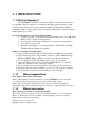
1.1 INTRODUCTION 1.1.1 What is Superpro? The SUPERPRO is a family of affordable, reliable, and fast universal IC device programmers. They are designed to communicate through a parallel (printer) or USB port(model dependent) and to operate with Intel 80486- and Pentium-based IBMcompatible desktop computers and notebook computers. Menu-driven software interface makes them easy to operate. Programming hardware include the following items. 1.
Up arrow key = Down arrow key = Unless stated otherwise, keystrokes are not case-sensitive. e.g.: Both 'A' and 'a' are acceptable. 1.3.2 System Requirements The minimum requirement is as follows: 1. A 486 or Pentium PC, desktop or laptop. 2. One parallel port, such as LPT1 (278H), LPT2 (378H), or LPT3 (3BCH). 3. MS Windows9x, NT or 2000 operating system (model dependant) 4. Diskette drive (3.5" 1.44 Mbytes) or CD-ROM for installation 5.
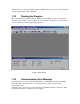
switch and observe the power LED coming on bright. Please be sure not to insert any chip onto the programmer socket at this time. 1.2.3 Running the Program Please run the main program for the programmer. If everything is set up correctly, then the main screen should come up without any error message. At this point, you may select a device and proceed with programming operation. Figure1. Main Screen 1.2.
1.2.5 Device Insertion For chips in DIP package Follow the reference diagram next to the socket. Chips are always inserted at the bottom line of the ZIF socket with the pin 1 facing toward upper left corner. For some low-end models, some devices may need to be inserted in a non-standard way. Instruction for insertion of such devices will appear on the screen when the selection of the device is made.
selection of the device to read from. Click on Run from the main screen, which will pop up the Function screen. Click on the Read function, which copies the data from the master chip into the buffer. At this point you may go to the buffer and examine the data to see if it is loaded correctly. The data may be saved to a disk for later use. Program device: Insert blank chip into the socket and enter on Program function. Device should begin programming at this time followed by verification.
Figure 8 Data type 2.1.2 Save This selection will save the current data in the buffer to disk. For E(E)PROM, BPROM or MCU device types, Save File window will pop up. Select the folder and filename to be saved under. Next, File Type dialog box will pop up for selecting file type to be saved under. For PLD devices, the Save JED File dialogue box will pop-up to enter the file name. 2.1.3 Exit This command closes the programmer software and returns you to the control of the operating system. 2.
Figure 9. Edit Buffer Locate The function is convenient for locating a set of data for editing. In the Locate Buffer dialog box, key in the address you wish to see displayed and press OK. The cursor will blink at the address specified in the space marked New Address. Fill The function will bring up the Fill Buffer dialogue box. It consists of the Start Address, End Address, Fill Data input lines, OK and Cancel buttons.
Swap MSB and LSB byte order for the specified word width in the address range. Figure 13. Swap Buffer Radix Toggles between HEX and DEC (Decimal) memory address display. Search Searches for a combination of HEX/ASCII codes (search string). Next Performs the next search for the search string in Search. 2.2.2 Encryption Table The Load Encryption Table, with its two sub-menus, manages an encryption array. The two sub-menus will appear only if the chip selected is equipped with an encryption array.
This opens the Vector Buffer Edit window. If a test vector table is included in the JEDEC file, the software will load the test vector table to the buffer automatically when the JEDEC file is loaded. Refer to the following when editing the test vector. Z: High impedance state X: Don't care state N: Vcc and ground (output pins are not tested) H: Output logic High (Voh) L: Output logic low (Vol) C: Clock pin 1: Input logic High (Vih) 0: Input logic Low (Vil) 2.
Figure 15. Run Program The function writes the data from the buffer into the chip. The Verify function is performed automatically after programming. If an error occurs, the error message will be displayed along with the addresses and data of the chip and buffer where the error occurred. Any other result will be displayed in the message section. The current address is incremented in the Current Address display window while the chip is being programmed or verified.
Verify The function compares the content of the buffer to that of the chip. If there is any discrepancy, verify failure message and the address where it started failing will be displayed in the Message window. For PROM or MCU devices, verification of range between start and end addresses (specified by you) is available. Blank Check The function checks if the device is in blank state. For a ROM or MCU, checking of a range between a start and end address (specified by you) is possible.
Chip End Input an address for the chip where you would like a selected function of downloading or uploading to end. This is normally set to the end address of the chip. Buff Start This sets the address in the buffer where file loading begins. By changing the address, a file can be loaded at any desired location. Buff End This sets address in the buffer where file loading ends. By changing the address, a file can end loading at any desired location.
Edit box. When the highlighted cursor is placed over a name of the manufacturer, names of the devices for the manufacturer selected will be displayed instantly in the Device column. Type radio button allows you to select one of the different device types, such as, E/EPROM, PLD, MCU,etc. Select the device type first before selecting Manufacturer of a device. Search Edit box allows you to search device quickly. Figure 17. Select Device 2.3.
The Word Format window allows you to specify the data format loaded into the buffer. The default setting is Byte format. Word or Double Word format may be selected. For programming into byte- wide chip further selection to byte level is needed. Byte 8-bit data format is selected.
Figure 18. Word Format 2.4. Test: The SUPERPROs can test logic ICs and RAM devices, as well as perform vector testing on PLDs. The user-friendly software provides an easy interface for loading files, editing test patterns, and downloading and uploading data between the buffer and the device. The SUPERPROs provide a 74/54 and 4000/45000 TTL/CMOS logic device test library, and memory test algorithms. Following sections describe the functions available for testing logic ICs and RAMs.
L: C: 1: 0: Output Logic Low (Vol) Clock pin Input Logic High (Vih) Input Logic Low (Vil) 2.4.2 Edit Pattern This selection is used for editing a test pattern in the library. When you are in the Test menu, click on Edit Pattern. This brings up the Select Chip to Edit dialogue box. It consists of Select Type input line, a Device List viewer, and the OK and Cancel buttons. You can enter the device name into the input line, or select from the list viewer.
deleted and you will return to the main menu. Make sure you have made the correct selection. The only way to retrieve a deleted test pattern is to recreate the pattern (using 'New Pattern'). 2.4.4 TTL&CMOS test This selection tests TTL and CMOS devices. Click on the sub-menu TTL & CMOS Test in the Test menu. This will open the Select Chip to Test dialogue box. Highlight the device that you wish to test, and then click on the OK button.
Option: Check Insertion Test if you want the programmer to do an insertion test before any operation on the device. Check Beeper if you want the programmer to beep after any operation. . Initialize Programmer: Clicking on communication will search the programmer through all possible parallel port. If it finds the programmer, the communication will be successful. If not, Error message will appear.
e) Start programming. Figure 21 .Auto Increment 2.5.3 Load config file Operational Configuration is created automatically during operation and saved as a file in the BIN directory. When the program is started the file is loaded automatically to restore the previous operational status, which includes device related information, parallel port and other setup information. The file may be edited and saved for later use. 2.5.4 Save config file The selection brings up the Save Config File dialogue box.
XELTEK software has been designed to require a minimum of technical support. The program comes with a comprehensive User's Guide. If you cannot find the answer in the manual, you can turn to your dealer, or distributor, or to XELTEK. XELTEK Technical Support: Should your local distributor be unable to solve your problem, XELTEK provides telephone technical assistance during normal business hours (8:00 am to 6:00 p.m. EST).
Modify, copy, or transfer the User's Guide, other documentation or any copy. Reverse engineer, decompile, or disassemble any program module or security device. This license is effective until terminated. You may terminate it by destroying or returning the program, manuals, and all copies thereof. This license will terminate if you fail to comply with any term or condition of this agreement.
Invalid File Type: An input file with wrong format is selected. Please select right format for the input file. 3.2.2 Init Programmer Error(Programmer initialization error): Communication searches no programmer connected. Software only works in demo mode. Make sure programmer powering on, search programmer with communication (See Setting sub menu) again. 3.2.3 Algorithm file Not Found: Every device has an algorithm file. After selecting the device, algorithm file will be loaded (DLL file).