
Instructions / Assembly


Page 10
Stealth
™
Series Pumps Installation and Operation Manual
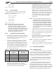
RECOMMENDED MINIMUM WIRE SIZE FOR SHP PUMPS*
Distance from Sub-Panel 0-50 Feet 50-100 Feet 100-150 Feet 150-200 Feet
Pump Model
Branch Fuse AMPs
Class: CC, G, H, J, K,
RK, or T
Voltage Voltage Voltage Voltage
230VAC 115VAC 208-230 VAC 115 VAC 208-230 VAC 115 VAC 208-230 VAC 115 VAC 208-230 VAC 115 VAC
SHPF .50HP/SHPM .75HP 15A 15A 14 12 12 8 10 6 8 6
SHPF .75HP/SHPM 1.0HP 15A 15A 14 12 12 8 10 6 8 6
SHPF 1.0HP/SHPM 1.5HP 15A 20A 12 10 10 8 8 6 6 4
SHPF 1.0-3PH 15A N/A 14 N/A 12 N/A 10 N/A 8 N/A
SHPF 1.5HP/SHPM 2.0HP 15A N/A 12 N/A 10 N/A 8 N/A 6 N/A
SHPF 1.5-3PH 15A N/A 12 N/A 10 N/A 8 N/A 6 N/A
SHPF 2.0HP/SHPM 2.5HP 15A N/A 12 N/A 8 N/A 6 N/A 6 N/A
SHPF 2.0-3PH 15A N/A 12 N/A 10 N/A 8 N/A 6 N/A
SHPF 3.0HP 20A N/A 10 N/A 8 N/A 6 N/A 4 N/A
SHPF 3.0-3PH 15A N/A 12 N/A 8 N/A 6 N/A 6 N/A
SHPF 5.0 25A N/A 10 N/A 8 N/A 6 N/A 6 N/A
SHPF 1.0HP-2-SPD (1) 15A N/A 12 N/A 10 N/A 8 N/A 6 N/A
SHPF 1.5HP-2-SPD (1) 15A N/A 12 N/A 10 N/A 8 N/A 6 N/A
SHPF 2.0HP-2-SPD (1) 15A N/A 12 N/A 8 N/A 6 N/A 6 N/A
SHPM 1.5HP-2-SPD (1) 15A N/A 12 N/A 10 N/A 8 N/A 6
N/A
SHPM 2.0HP-2-SPD (1) 15A N/A 12 N/A 10 N/A 8 N/A 6 N/A
SHPM 2.5HP-2-SPD (1) 15A N/A 12 N/A 8 N/A 6 N/A 6 N/A
*Assumes three (3) copper conductors in a buried conduit and 3% maximum voltage loss in branch circuit. All National Electrical Code (NEC) and local codes must
be followed. Table shows minimum wire size and branch fuse recommendations for a typical installation per NEC.
(1) Two-speed pumps are not rated for use with 208 VAC.
Table 2. Recommended Minimum Wire Size
CAUTION
The pump must be permanently connected to a dedicated
electrical circuit. No other equipment, lights, appliances
or outlets may be connected to the pump circuit, with
the exception of devices that may be required to operate
simultaneously with the pump, such as a chlorinating
device or heater.
3.2.3 Electrical Wiring
1. The pump motor must be securely and adequately
grounded using the green screw provided. Ground
before attempting to connect to an electrical power
supply. Do not ground to a gas supply line.
2. Wire size must be adequate to minimize voltage
drop during the start-up and operation of the
pump. See Table 2 for recommended wire sizes.
3. Insulate all connections carefully to prevent
grounding or short-circuits. Sharp edges on
terminals require extra protection. To prevent wire
nuts from loosening, tape them using a suitable,
listed (UL, ETL, CSA) electrical insulating tape.
For safety, and to prevent entry of contaminants,
reinstall all conduit and terminal box covers. Do
not force connections into the conduit box.
4. To configure the internal wiring of the pump motor
for the correct voltage, refer to the diagram on the
motor data plate.
CAUTION
Failure to provide data plate voltage (within 10%) during
operation will cause the motor to overheat and void the
warranty.
3.2.2 Bonding and Grounding
1. The motor frame must be grounded to a reliable
grounding point using a solid copper conductor,
No. 8 AWG or larger. In Canada, No. 6 AWG or
larger must be used. If the pump is installed within
five (5) feet of the inside walls of the swimming
pool, spa, or hot tub, the motor frame must be
bonded to all metal parts of the swimming pool,
spa, or hot tub structure and to all electrical
equipment, metal conduit, and metal piping within
five (5) feet of the inside walls of the swimming
pool, spa, or hot tub.
2. Bond the motor using the provided external lug.
WARNING
To avoid the risk of property damage, severe personal
injury, and/or death, make sure that the control switch or
time clock is installed in an accessible location so that
in the event of an equipment failure or a loose plumbing
fitting the equipment can be turned off. This location
must not be in the same area as the pool pump, filter,
and other equipment.
WARNING
To avoid the risk of property damage, severe personal
injury, and/or death, always disconnect the power source
before working on a motor or its connected load.