
User Manual


- 58 -
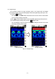
3.5 How to determine depths and sample scan data
The reflected waves
shown in the scan example in Figure 3-20 are reflections of rebar. (↓ position)
The position of the object to be probed (e.g., reinforcing steel) in the traveling direction is determined as
the peak of the reflected wave.
An approximate depth (covering depth) of the object to be probed (e.g., reinforcing steel) is determined
as the center of the reflected wave.
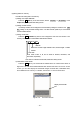
Perform depth calibration (see Section
3.2.6 Depth) to reduce the error in the depth (covering depth) of
the object being probed (such as rebar). Use the A-mode waveform from BA-mode (see Section 3.3.1
Mode switching) to determine the position of the object to be probed.
The position of the object to be probed (such as rebar) is shown by the peak on the right side of the
A-mode waveform. Match the cursor to the peak position to determine the depth.
Figure 3-20 Scan example
:Position of rebar shown
among the reflected waves
of the scan results (The
mark is not actually
shown in the scan results.)
200mm
200mm 200mm
60mm
120mm
180mm
240mm
300mm
測定方
スタート
Vertical cross sectional drawing
of object to be probed
:Φ=10cm rebar
Measurement direction
Start