Chapter 8 DETAIL PERFORMANCE SETTING Chapter 9 MAINTENANCE AND CHECK 9 - 1 R O U TI N E M AI NT E N AN C E For operating the radar equipment in the good conditions, it is necessary to make the maintenance work as described below. If maintenance is made properly, troubles will reduce. It is recommended to make regular maintenance work. Common points of maintenance for each unit are as follow: Clean the equipment.
Chapter 9 MAINTENANCE AND CHECK 9 - 2 M AI N T EN A N C E OF E A C H U NI T 9-2-1 SCANNER NKE-1066 DANGER When conducting maintenance work on the antenna, make sure to turn its main power off. Failure to comply may result in electrocution or injuries.
Chapter 9 MAINTENANCE AND CHECK 9-2-2 SCANNER NKE-2044 DANGER When conducting maintenance work on the antenna, make sure to turn its main power off. Failure to comply may result in electrocution or injuries.
Chapter 9 MAINTENANCE AND CHECK 9-2-3 DISPLAY NCD-2256 DANGER When cleaning the display screen, do not wipe it too strongly with a dry cloth. Also, do not use gasoline or thinner to clean the screen. Failure to comply will result in damage to the screen surface. Dust accumulated on the screen will reduce clarity and darken the video. For cleaning it, wipe it with a piece of soft cloth (flannel or cotton). Do not wipe it strongly with a piece of dry cloth nor use gasoline or thinner.
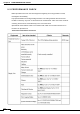
Chapter 9 MAINTENANCE AND CHECK 9 - 3 P E R F OR M A NC E C H EC K Make operational check on the radar equipment regularly and if any problem is found, investigate it immediately. Pay special attention to the high voltage sections in checking and take full care that no trouble is caused by any error or carelessness in measurement. Take note of the results of checking, which can be used effectively in the next check work. Operational check shall be made in accordance with Table 4.
Chapter 9 MAINTENANCE AND CHECK 9-3-1 TEST MENU The performance status of this radar equipment can be checked on the Test Menu. 9-3-2 SYSTEM INFORMATION Displays the current system information. (software version information). 9-3-3 SYSTEM TIME Displays the following system time information.
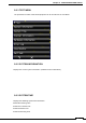
Chapter 9 MAINTENANCE AND CHECK 9-3-4 SCANNER INFORMATION Displays the following scanner information. ■ Transmitted output power ■ Motor Type ■ Magnetron Current 9-3-5 HARDWARE INFORMATION Displays the following hardware information. ■ Serial Number ■ MAC Address ■ Temperature 9-3-6 ERROR LOG The error log displays previously occurred system alarms with the dates and times when they occurred. 9-3-7 LINE MONITOR Serial communication data can be seen on the built-in Line monitor.
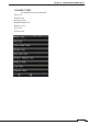
Chapter 9 MAINTENANCE AND CHECK 9-3-8 SELF TEST The following tests can be performed.
Chapter 9 146 MAINTENANCE AND CHECK
Chapter 9 MAINTENANCE AND CHECK 9 - 4 R E P L AC E M EN T O F MAJ O R P A R T S 147
Chapter 9 MAINTENANCE AND CHECK 9-4-1 PARTS REQUIRED FOR PERIODIC REPLACEMENT Here are parts required for periodic replacement. PARTS NAME 148 1. MAGNETRON 2.
Chapter 9 MAINTENANCE AND CHECK 9 - 5 F A U L T FI N DI NG 9-5-1 ALARMS AND OTHER DISPLAY LISTS 9-5-2 FUSE 9 - 6 T R O UB L E S H OO T IN G 9-6-1 INCLUDED ACCESSORIES 9-6-2 SPECIAL PARTS Location Parts No.
Chapter 9 MAINTENANCE AND CHECK 9-6-3 CIRCUIT BLOCK TO BE REPAIRED JMA-1032 Location Circuit Block Type Remarks Scanner Motor unit H-7BDRD0053 Scanner Modulation circuit CME-396 Include IF Amplifier Scanner Micro wave unit Transmitter/ receiver CMN-924/NZT-1066 Include Receiver frontend Display Unit Power Supply circuit CBD-1928 Display Unit Process Circuit CDC-1433 Display Unit LCD Panel NZP-2256 JMA-1034 Location 150 Circuit Block Type Remarks Scanner Motor unit H7BDRD0052
Chapter 9 MAINTENANCE AND CHECK 151
Chapter 10 AFTER-SALE SERVICE Chapter 10 AFTER-SALE SERVICE 1 0 - 1 K E E PI N G P E RI O D O F M AI N T EN A NC E P A R TS Keeping period of maintenance parts is ten years from the production is discontinued. 1 0 - 2 W H E N Y O U R E Q U E ST F O R R E P AI R If you suppose the product may be out of order, read the description in "9-2-5 FAULT FINDING" and "9-2-6 TROUBLE SHOOTING", and check the suspected point again.
Chapter 10 AFTER-SALE SERVICE 1 0 - 4 R A DA R F AI L U RE C H E C K LI S T 153
Chapter 11 DISPOSAL Chapter 11 DISPOSAL 1 1 - 1 DI S P O S A L O F T H E U NI T When disposing of this unit, be sure to follow the local laws and regulations for the place of disposal.
Chapter 11 DISPOSAL 1 1 - 2 DI S P O S A L O F U S E D M A GN E T R ON A magnetron is used for the scanner (NKE-1066) (NKE-2044). ☆ When the magnetron is replaced with a new one, return the used magnetron to our dealer or business office. For detail, consult with our dealer or business office.
Chapter 11 156 DISPOSAL
Chapter 12 SPECIFICATIONS Chapter 12 SPECIFICATIONS NKE-1066 scanner NCD-2256 display 1.
Chapter 12 SPECIFICATIONS 1 2 - 1 S C A NN E R DI M E N SI O N 12-1-1 NKE-1066 NKE-1066 1.
Chapter 12 SPECIFICATIONS 12-1-2 NKE-2044 160
Chapter 12 SPECIFICATIONS 1 2 - 2 DI S P L A Y DI M EN SI O N 12-2-1 NCD-2256 161
Chapter 12 162 SPECIFICATIONS
Chapter 12 SPECIFICATIONS 1 2 - 3 E Q UI PM E N T OU T LI N E 1)This equipment is a marine radar for vessels and work boats which consists of the display unit including 7 inch wide VGA color LCD Monitor unit, Keyboard unit, Processing unit and consists of the 1.5 ft /2ft radome type scanner unit. The processing unit uses SOC (LUPIM) developed by JRC and the LCD monitor unit uses panel with touch sensor (resistance film type). The operation can be realized intuitive and simple.
Chapter 12 SPECIFICATIONS 12-3-4 SYSTEM DIAGRAM JMA-1030 Series system diagram 1.5feet Scanner Unit (NKE-1066) Radome diameter 450mm 2feet Scanner Unit (NKE-2044) Radome diameter 620mm CFQ9924-5,10,15,20,300 *STANDARD LENGTH 10m OPTION: (cablelength:5m/15m/20m/30) JMA-1032 RADAR JMA-1034 RADAR External Navigational Signal input. NMEA 3 input ports (GPS,AIS,DEPTH) Ship’s Main Power (10.8-31.2VDC) CFQ-9900 (cable length 2m) *INCLUDING FUSE IN PLUS LINE FUSE TYPE: 7.
Chapter 12 SPECIFICATIONS 1 2 - 4 G E N E RA L S P E C IFI C A TI O N S (1) Class of Emission P0N (2) Display Color Raster Scan (3)Display capability WVGA (800x480dots) Screen (4) Screen 7-inch Color LCD with touch sensor (resistance film type) (5) Range Scale 0.0625, 0.125, 0.25, 0.5, 0.75, 1.
Chapter 12 SPECIFICATIONS 1 2 - 5 S C A NN E R 12-5-1 SCANNER (NKE-1066) SPECIFICATION (1) Dimensions Height 231mm×Diameter of radome 450mm (2) Mass Approx. 5.5kg (3) Polarization Horizontal (antenna length 1.5 feet) (4) Antenna Directivity Horizontal Beam Width (-3dB) 5.2° Vertical Beam Width (-3dB) 25° Side lobe Level Less than -21dB (less than ±10° from the main lobe) (5) Rotation Approx.
Chapter 12 SPECIFICATIONS 12-5-2 SCANNER (NKE-2044) SPECIFICATION (1) Dimensions Height 280mm×Diameter of radome 620mm (2) Mass Approx. 10.5kg (3) Polarization Horizontal (antenna length 2 feet) (4) Directional Characteristic Horizontal Beam Width (-3dB) 4° Vertical Beam Width (-3dB) 25° Side lobe Level -21dB or less (less than ±10° from the main lobe) (5) Rotation Approx.
Chapter 12 SPECIFICATIONS 1 2 - 6 DI S P L A Y 12-6-1 INTEGRATED DISPLAY UNIT (NCD-2256) 1) Structure Desk Top Integrated Type (LCD Monitor Unit/Keyboard Unit/Processor Unit Integrated Structure) Vertical installation only desk top integrated type Option: Overhead Mounted kit installation 2) Dimensions Height 235.2mm × Width 162mm × Depth 77.3mm (The U style mount base and the both sides knob bolts are included.) 3) Mass Approx. 1.
Chapter 12 SPECIFICATIONS 14) Variety of Pulse width SP1/ SP2/ SP3/ MP1/ MP2/ LP1/ LP2 (LP2 is JMA-1034 only) 15) Target enhance 3 stages 16) Plotting 3 marks 17) Display color Radar echo 16 stages, 8 colors (Yellow, Green, Blue, White, Magenta, Gold, Amber, Color) Radar trails 1 stage, Time trails: 3 colors (Green, Blue, Cyan) Continuous trails: 3 colors (Green, Blue, Cyan) Background PPI: 3 colors (Black, Blue, White) Characters 7 colors (White, Cyan, Green, Black, Red, Gold, Amber) AIS/TT
Chapter 12 SPECIFICATIONS 12-6-2 OPERATIONAL PANEL 1) Structure Integrated on the display unit PWR/CLR 2) Key Short push: Power ON ( at the time of Power OFF) Long push: Power OFF PWR/CLR 3) Knob Controller Short push: input cancel, back to a up-layer PUSH : Menu or Icon selection and execution, control EBL/VRM, number input, Enter, etc. PUSH + rotation: Brilliance control 4) Touch control Tap: Menu or Icon selection and execution, control, etc.
Chapter 12 SPECIFICATIONS 1 2 - 7 IN P U T/ O U T PU T SI G N AL Telecommunications standard NMEA0183 / 61162 -1/2 Communications protocol 4800 bps, start 1bit, data 8bit, stop 1bit, non parity Input sentence NMEA0183: V1,5: GGA/ GLL/ RMC V2,0: GGA/G LL/ RMC/ZDA V2,3 : GGA/GLL/RMC/GNS/ZDA (Talker=”GP” etc.
Chapter 12 SPECIFICATIONS 12-7-2 OUTPUT POSSIBLE SIGNAL (THREE-LINE GPS/HDG/TTM) (1) Navigation equipment Radar date: RSD Own ship’s data: OSD TT data: TTM, TTL, TTD Latitude/ Longitude data: GGA, RMC, GNS, GLL, COG/SOG: VTG (Received GPS data) Bearing signal: THS, HDT (Received GPS Compass data) (2) External Buzzer Factory presetting: normal open contacts (3) Output RGB signal To incorporate optional kit (NQA-2447) is necessary ※In this case, waterproofing (IPx5) of rear side of display unit is
Chapter 13 APPENDIX Chapter 13 APPENDIX NKE-1066(1.
Chapter 13 APPENDIX NKE-2044(2FT) SCANNER INTRCONNECTION DIAGRAM FIG A2 APPENDIX-2
Chapter 13 APPENDIX NCD-2256 DISPLAY UNIT INTER CONNECTION DIAGRAM FIG A3 APPENDIX-3
Chapter 13 APPENDIX JMA-1030 PRIMARY POWER SUPPLY DIAGRAM FIG A4 APPENDIX-4
Chapter 13 APPENDIX JMA-1030 INTER CONNECTION DIAGRAM FIG A5 APPENDIX-5
Chapter 13 APPENDIX 90mm 140 mm FIG A6 APPENDIX-6
Chapter 13 APPENDIX O P E RA TI O N S H E E T 90mm GAIN RAIN SEA VRM GURDZONE MARK CURSOR SETTING MENU TT ACTIV TT ST-BY DAY 140 mm AIS ACTIV USER1 NIGHT TX-STBY AIS SLEEP USER2 MODE RIVER RANGE MOB BRILLIANCE EBL OFFCENTER MODE STANDARD MODE COAST MODE FIOAT MODE OFF FIG A7 APPENDIX-7
MENU FUNCTION LIST M EN U F U NC TI O N LI S T Main Menu Item Setting Contents 1. RADAR Echo 1. Pulse Length SP/MP/LP 2. IR OFF / Low / Middle / High 3. Target Enhance OFF / Level1 / Level2 / Level3 4. Process OFF / 3Scan COREL / 4Scan COREL / 5Scan COREL / Remain / Peak Hold 5. Zoom OFF / ON 6. Video Latitude Narrow / Normal / Wide1 / Wide2 7. Video Noise Rejection OFF / Level1 / Level2 / Level3 8. Timed TX OFF / ON 2. Tuning 3. Motion Mode 1. Motion RM, TM 2. Bearing Mode HUP/NUP/CUP 4. Radar trail 1.
MENU FUNCTION LIST Item Setting Contents 4. CPA Ring Display OFF / ON 5. Target Number Display 1. TT OFF / ON 2. AIS OFF / ON 6. ALR Alarm From AIS OFF / ON 7. AIS Display Targets 20 / 30 / 40 / 50 8. AIS List Display OFF / ON 8. NMEA Info.
MENU FUNCTION LIST Initial setting Menu Item 1. Basic Adjustment 1. Bearing Adjustment 2. Range Adjustment 3. Tune Adjustment 4. Antenna Height 5. Noise Level 6. Language 2. RADAR Echo 1. Main Bang Suppression 1. MBS Level 2. MBS Area 2. Target Enhance Level 3. Gain Preset 4. STC 1. STC Curve Select 2. STC Slope Correction 3. STC Offset 1. FTC 1. FTC Curve Select 2. FTC Slope Correction 3. FTC Offset 6. RADAR Alarm 1. RADAR Alarm1 Level 2. RADAR Alarm2 Level Setting Contents 0.0 - 359.
MENU FUNCTION LIST Item Setting Contents 7. COM Port Setting 1. Baud Rate 1. NMEA1 2. NMEA2 3. NMEA3 2. RX Port 1. GPS 2. Log 3. 2axis Log 4. Depth 5. Temperature 6. Wind 7. WPT 8.Rate of Turn 9. Rudder 3. TX Port 1. TTM 2. TLL 3. TTD 4. TLB 5. GGA 6. GLL 7. RMC 8. GNS 9. VTG 10. THS 11. HDT 12. OSD 13. RSD 4. TX Data Format 1. TX Interval 2. NMEA Version 3. NMEA Talker 5. Target Info. TX 1. TX Target 2. TTM Range Accuracy 3. TT Average Mode 4.
MENU FUNCTION LIST Item Setting Contents 13. Send Data 14. GPS Adjust 1. Position 2. Antenna Height 3. Time 4. Date 5. Master Reset 6. Send Data 3. Beacon Setting 1. Station Select 2. Frequency 3. Baud Rate 4. Send Data 4. SBAS Setting 1. Satellite Search 2. Ranging 3. SBAS Satellite Number 4. Send Data 9. Control 1. Touch Panel Calibration 2. Bearing Reference (*NKE-2044 only) 3. Buzzer 1. Key ACK 2. Operation Error 3. CPA/TCPA 4. AZ/Alarm Zone 5. Target Lost 6. System Alarm 10. Maintenance 1.
MENU FUNCTION LIST Item Setting Contents 6. Internal Setting 1. Internal Memory to USB 1. All Menu 2. RADAR Echo 3. Function Setting 4. Initial Setting Menu 5. Main Menu 6. Mark Setting 7. Adjust Menu (*NKE-2044 only) 8. System Information 1 (*NKE-2044 only) 9. System Information 2 (*NKE-2044 only) 2. USB to Internal Memory 1.All Menu 2. RADAR Echo 3. Function Setting 4. Initial Setting Menu 5. Main Menu 6. Mark Setting 7. Adjust Menu (*NKE-2044 only) 8. System Information 1 (*NKE-2044 only) 9.
MENU FUNCTION LIST Item Setting Contents 2. km 1. 0.15km 2. 0.3km 3. 0.5km (*NKE-2044 only) 4. 1.2km 5. 2km 6. 8km 7. 16km 8. 32km OFF / ON OFF / ON OFF / ON OFF / ON OFF / ON OFF / ON OFF / ON OFF / ON 1. 0.0625sm 2. 0.125sm 3. 0.25sm 4. 1sm 5. 2sm 6. 4sm 7. 8sm 8. 16sm 9. 24sm 10. 32sm 11. 48sm OFF / ON OFF / ON OFF / ON OFF / ON OFF / ON OFF / ON OFF / ON OFF / ON OFF / ON OFF / ON OFF / ON 3. sm 12. Display Screen 1. Own Vector Display 2. STBY Disp. Select 3. Operation Num Disp. 4.
MENU FUNCTION LIST Item Setting Contents 12. AZ/Alarm Zone 1. Color 2. Brilliance White/Green/Orange/Black/Red Level1/ Level2/ Level3/ Level4 ON/OFF 0.0 - 48.0 1. Alarm Sensitivity 2. Sensitivity Time OFF / ON 0 - 999sec 1. Alarm Sensitivity 2. Sensitivity Time OFF / ON 0 – 999sec 1. Alarm Sensitivity 2. Sensitivity Time OFF / ON 0 - 999sec 1. Alarm Sensitivity 2. Sensitivity Time OFF / ON 0 - 999sec 1. Alarm Sensitivity 2. Sensitivity Time OFF / ON 0 -999sec 1. Alarm Sensitivity 2.
MENU FUNCTION LIST Item Setting Contents 4. RX Data 1. GYRO 1. Alarm Sensitivity 2. Sensitivity Time OFF / ON 0 -999sec 1. Alarm Sensitivity 2. Sensitivity Time OFF / ON 0 -999sec 1. Alarm Sensitivity 2. Sensitivity Time OFF / ON 0 -999sec 1. Alarm Sensitivity 2. Sensitivity Time OFF / ON 0 -999sec 1. Alarm Sensitivity 2. Sensitivity Time OFF / ON 0 -999sec 1. Alarm Sensitivity 2. Sensitivity Time OFF / ON 0 -999sec 1. Alarm Sensitivity 2. Sensitivity Time OFF / ON 0 -999sec 1.
MENU FUNCTION LIST Item Setting Contents 2. System Time 1. Scanner Transmit Time 2. Scanner Motor Time 3. Scanner Running Time 4. Indicator Running Time 3. Scanner Information 1. Scanner Transmit Power 2. Motor Type 3. Magnetron Current 4. Hardware Information 1. Serial Number 2. MAC Address 5. Error Log 1. Display 2. Erase 6. Line Monitor 1. Scanner 2. NMEA1 3. NMEA2 4. NMEA3 7. Self Test 1. Key Test 2. Touch Panel Test 3. Buzzer Test 4. Key Light Test 5.
MENU FUNCTION LIST APPENDIX-18
Not use the asbestos JRC website http://www.jrc.co.jp/ Marine Service Department Telephone: +81-3-3492-1305 Facsimile: +81-3-3379-1420 e-mail tmsc@.jrc.co.jp Amsterdam branch Telephone: +31-(0)20-658-0750 Facsimile +31-(0)20-658-0755 e-mail service@jrceurope.com Seattle branch Telephone: +1-(0)206-654-5644 Facsimile: +1-(0)206-654-7030 e-mail service@jrcamerica.com 01JTM ISO 9001 and ISO 14001 Certified Code No.