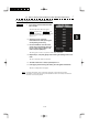
3.8 3.8 DISPLAY NAVIGATION INFORMATION (NEW INFORMATION DISPLAY) y yy DISPLAY NAVIGATION INFORMATION (NAV INFORMATION DISPLAY) Navigation information such as waypoint marks, and a maximum of 256 points of NAV lines, coastlines, depth contours, and NAV marks can be displayed, created, read, saved, corrected, and deleted. (This function is available only when navigation equipment is connected with the system.) Note: Navigation information is available between latitudes of 85ºN and 85ºS. 3.8.
3.8.2 Display Navigation Information (NAV Display Setting) The navigation information below can be displayed (ON) or hidden (OFF) individually. c Line 1 [Line 1] ― d Line 2 [Line 2] ---e Line 3 [Line 3] ‐― f Mark 1 [Mark 1] g Mark 2 [Mark 2] ★ h Mark 3 [Mark 3] + i Mark 4 [Mark 4] Y Procedure 1 Press [RADAR MENU] key. Press [6] key. Press [2] key. The NAV Display Setting Menu will appear. To determine whether to display each type of navigation information, press the corresponding numeric key.
.8 3.8.3 DISPLAY NAVIGATION INFORMATION (NEW INFORMATION DISPLAY) y yy Create/Edit Navigation Information (Edit User Map) Procedure 1 Press [RADAR MENU] key. Press [6] key. Press [3] key. Press [6] key. The Edit User Map Menu will appear. The Edit User Map enables the operations of the functions below. Clear Map Object: Clears all or an item of navigation information. Make Map Object: Creates navigation information. Correct: Corrects navigation information.
1 Clearing all or an item of navigation information (Clear Map Object) Procedure 1 Press [1] key while the Edit User MAP Menu is open. The Clear Map Object Menu will appear. Select the type of navigation information to be cleared, pressing the corresponding numeric key. Line1: Line2: Line3: Mark1: Mark2: Mark3: Mark4: Clears Line 1. Clears Line 2. Clears Line 3. Clears Mark 1. Clears Mark 2. Clears Mark 3. Clears Mark 4. All: Clears all items of navigation information.
3.8 2 DISPLAY NAVIGATION INFORMATION (NEW INFORMATION DISPLAY) y yy Making navigation information (Make Map Object) Procedure 1 Press [2] key while the Edit User MAP Menu is open. The Make Map Object Menu will appear. MAKE will appear in the CURSOR mode field at software button ② located at the bottom right corner of the radar display described in Section 2.3.3. 2 Select the type of navigation information to be made, pressing the corresponding numeric key.
3 Correcting a continuous line or moving a mark (Correct) Procedure 1 Press [3] key while the Edit User Map Menu is open. The navigation information correction mode will be activated. Correct will appear in the CURSOR mode field at software button ② located at the bottom right corner of the radar display described in Section 2.3.3. 2 Use the trackball to move the pointer to the vertex in a line to be corrected or the mark to be moved, and press [ENT] key.
3.8 4 DISPLAY NAVIGATION INFORMATION (NEW INFORMATION DISPLAY) y yy Deleting a continuous line or mark (Delete) Procedure 1 Press [4] key while the Edit User Map Menu is open. The navigation information deletion mode will be activated. Delete will appear in the CURSOR mode field at software button ② located at the top right corner of the radar display described in Section 2.3.3. 2 Use the trackball to move the pointer to the vertex in a line or the mark to be deleted, and press [ENT] key.
5 Inserting a vertex into a line (Insert) Procedure 1 Press [5] key while the Edit User MAP Menu is open. The navigation information insertion mode will be activated. Insert will appear in the CURSOR mode field at software button ② located at the top right corner of the radar display described in Section 2.3.3. 2 Use the trackball to move the pointer to the line that is to become a vertex, and press [ENT] key. The cross cursor mark will appear on the selected point.
3.8 3.8.4 DISPLAY NAVIGATION INFORMATION (NEW INFORMATION DISPLAY) y yy Set Navigation Information (User Map Setting) Procedure 1 Press [RADAR MENU] key. Press [6] key. Press [3] key. The User Map Setting Menu will appear. Select operation for navigation information, pressing the corresponding numeric key. The selected operation will be performed. Load: Loads navigation information. Unload: Unloads navigation information. Save: Saves navigation information. Erase: Erases navigation information.
[I] Entering the own ship’s position in manual mode (Own Ship Position) Use this function to edit the navigation information of any positions other than the own ship’s position. Procedure 1 Press [1] key while the User Map Setting Menu is open. The CODE INPUT Menu for entering latitude and longitude of the own ship position will appear. 2 Enter a value as the latitude (xx° xxx.xx’) using the numeric keys [0] to [9]. 3 To switch between north latitude and south latitude, turn the [MULTI] control.
3.8 DISPLAY NAVIGATION INFORMATION (NEW INFORMATION DISPLAY) y yy [II] Loading navigation information (Load User Map) Procedure 1 Press [2] key while the User Map Setting Menu is open. The Load User Map Menu will appear. 2 Press [2] key. The list of navigation information files saved in the system will appear. * Each time you press [1] key, the Device item is switched between INTERNAL and CARD2. INTERNAL: Reads saved data from the processor. CARD2: Reads saved data from CARD2.
[III] Initializing Navigation Information (Unload) Procedure 1 Press [3] key while the User Map Setting Menu is open. Display the window to select whether or not the information is to be initialized. 2 Press [1] key. The navigation information is initialized. This function can be executed for files that have been read and new navigation information currently being entered.
3.8 DISPLAY NAVIGATION INFORMATION (NEW INFORMATION DISPLAY) y yy [IV] Saving navigation information (Save User Map) This function is available only when navigation equipment is connected with the system or the own ship’s position is entered in manual mode. Procedure 1 Press [4] key while the User Map Setting Menu is open. 2 Press [2] key. The Save User Map Menu will appear. * Each time you press [1] key, the Device item is switched between INTERNAL and CARD2. INTERNAL: Saves data in the processor.
[V] Erasing navigation information from memory (Erase User Map) Procedure 1 Press [5] key while the User Map Setting Menu is open. 2 Press [2] key. The Erase User Map Menu will appear. * Each time you press [1] key, the Device item is switched between INTERNAL and CARD2. INTERNAL: Erases saved data from the processor. CARD2: Erases saved data from CARD2. To select CARD2, insert the flash memory card, in which data has been saved, into card slot 2 (upper stage).
3.8 DISPLAY NAVIGATION INFORMATION (NEW INFORMATION DISPLAY) y yy [VI] Shifting the display position of navigation information to a correct position (Shift) If the display position of navigation information is incorrect, it can be shifted to the correct position in manual mode. Procedure 1 Press [7] key while the User Map Setting Menu is open. Shift will appear in the CURSOR mode field of software button ② located at the top right corner of the radar display described in Section 2.3.
3.8.5 Set and Display Geodetic System To create navigation information, set the geodetic system that is used with the connected navigation equipment. When navigation information is loaded, the geodetic system used when the navigation information was saved, is displayed. Make sure that the displayed geodetic system is identical to the one used with the navigation equipment. If the two geodetic systems are different, the positions of navigation information on the radar display will be shifted.
3.8 DISPLAY NAVIGATION INFORMATION (NEW INFORMATION DISPLAY) y yy Geodetic System List No. 0 1 2 3 4 5 6 7 8 9 10 11 12 13 14 15 16 17 18 19 20 21 22 23 24 25 26 27 28 29 30 31 32 33 34 35 36 37 38 39 40 41 42 43 44 45 46 47 48 49 Name WGS-84 WGS-72 Japan North American 1927(U.
3.9 3.9.1 APPLIED OPERATIONS Set Radar Signal Processing (Process Setting) This function enables the setting of detail information about radar signal processing. Procedure 1 Press [RADAR MENU] key twice. Press [6] key. The Process Setting Menu will appear. Detail information about radar signal processing can be set by changing the settings of the menu items. Note: After the settings for radar signal processing are changed, small targets may not be displayed or unwanted waves may not be suppressed.
3.9 APPLIED OPERATIONS y yy [2] Video Noise Rejection • • • • This function rejects signals that assumed as noise and clutter in radar videos. Select OFF to display radar videos like analog signals. Select LEVEL1 or LEVEL2 to suppress noise and clutter. Select LEVEL1 or LEVEL2 to superimpose-display the chart. OFF : Turns off the noise rejection function, and displays all signals. Targets are popped up from noise and displayed like analog signals.
[5] 2nd Process Mode • Set the second video process mode for the outside of a specific area. • This function is enabled when RANGE FIX or AUTO is selected in [4] Process Switching. Video process modes PROC OFF Correlation 3 SCAN COREL Correlation Off : Short : 4 SCAN COREL Correlation Medium : 5 SCAN COREL Correlation Long : REMAIN PEAK HOLD Afterimage Afterimage Short: Long : Select this mode in general. Select this mode when many rain/snow clutter returns are detected.
3.9 APPLIED OPERATIONS 3.9.2 y yy Set Radar Trails (RADAR Trails Setting) This function enables the setting of detail information about radar trails processing. Procedure 1 Press [RADAR MENU] key twice. Press [7] key. Alternatively, hold down the [TRAILS] key until the menu appears. 3 The RADAR Tails Setting Menu will appear. Detail information about radar trails processing can be set by changing the settings of the menu items.
[4] Trails Reduction • Make a setting for thinning radar trails. • The effect of thinning increases in order of LEVEL1 → LEVEL2 → LEVEL3 . • Radar videos do not become obscure because of the thinning of radar trails. OFF : Disables the Trails Reduction function. LEVEL1 : Enables the Trails Reduction function. (Effect: Low) LEVEL2 : Enables the Trails Reduction function. (Effect: Modest) LEVEL3 : Enables the Trails Reduction function.
3.9 APPLIED OPERATIONS y yy Load and save of the Rdar trails. Procedure 1 Press [RADAR MENU] key twice. Press [7] key. Alternatively, hold down the [TRAILS] key until the menu appears. Press [9] key. The RADAR Tails Setting Menu will appear. [1] Loading Trails File • Presse [1] key. The saved trail files are displayed. • Select the file to be loaded Confirmation warining is displayed. Select “Yes” for loading. It takes a few second to be loded.
[3] Erasing Trails File • Presse [3] key. The saved trail files are displayed. • Select the file to be erased. Confirmation warining is displayed. Select “Yes” for erasing. Note: Deleted files can not be restored, so Erase files carefully. Erasing the displayed trails partially. Erasing the part of the displayed trails by using the cursor as a eraser. Note: Deleted trails can not be restored, so Erase them carefully. Procedure 1 Press [RADAR MENU] key twice. Press [7] key.
3.9 APPLIED OPERATIONS y yy [3] Eraser Size Press [3] key. z Eraser size lit is displayed. z Select the size of the eraser.
3.9.3 Set Cursor (Cursor Setting) This function enables the setting of detail information about cursor operation and display. Procedure 1 Press [RADAR MENU] key. Press [3] key. Press [6] key. The Cursor Setting Menu will appear. Detail information about cursor operation and display can be set by changing the settings of the menu items.
3.9 APPLIED OPERATIONS y yy [2] Cursor Length • Set the length of the cross cursor mark on the radar display. SHORT : Cuts the cross cursor mark in length. LONG : Makes the cross cursor mark twice as long as when SHORT is selected. [3] Cursor Pattern • The type of the cross cursor mark displayed of the display is selected. : Type 1 is selected for the cross cursor mark 1 displayed in the radar display. : Type 2 is selected for the cross cursor mark 2 displayed in the radar display.
3.9.4 Set Screen(Screen Setting) This function enables the setting of detail information about screen display. Procedure 1 Press [RADAR MENU] key. Press [4] key. The Screen Setting Menu will appear. Detail information about screen display can be set by changing the settings of the menu items. Graph Display Press the graph button to see the registered graph. To register a graph, hold down the graph button or use Graph Panel Setting menu described on the next page.
3.9 APPLIED OPERATIONS y yy [3] Graph Settings (Graph Panel Setting) Set the functions of a graph to be associated with the graph button. The function shown in the parentheses is prioritized. Therefore, specify a graph to be displayed while the prioritized function is not active. 1. Panel 1 (Target): A graph registered here can be displayed while target information is not displayed. 2. Panel 2 (Marker): A graph registered here can be displayed while the marker function is not in use. 3.
Wind/Current Graph • The wind direction and speed display function (Wind) is registered with the graph button when "Wind" is selected in the graph setting menu. • Press the Wind button to call up numerical values and a graph for the received wind direction and speed information. DIR/DIST EXP Display • Cursor, EBL, and VRM values are displayed in a larger font. • While the cursor is moving within the PPI screen, the cursor information is displayed in a larger font.
3.9 APPLIED OPERATIONS y yy Depth Graph Display • The water depth display function (Depth) is registered with the graph button when "Depth" is selected in the graph setting menu. • Press the Depth button to call up numerical values and a graph for the received water depth information. 3 Displaying Water Depth Graph (Depth Graph Setting) • Set the water depth graph display method. Procedure 1 Press [RADAR MENU] key. Press [4] key. Press [4] key. The Depth Graph Setting Menu will appear.
Depth Range • Select the depth range on the water depth graph. 50m : Sets 50 m as the depth range. 100m : Sets 100 m as the depth range. 250m : Sets 250 m as the depth range. AUTO : Uses the depth range in the DPT sentence included in received data. Depth range Time Table • Select the time range on the water depth graph. 10min : Sets 10 minutes as the time range. 15min : Sets 15 minutes as the time range. 30min : Sets 30 minutes as the time range. 60min : Sets 60 minutes as the time range.
3.9 APPLIED OPERATIONS y yy Water Temperature Display (Temp Graph) • The water temperature display function (Temp) is registered with the graph button when "Temp" is selected in the graph setting menu. • Press the Temp button to call up numerical values and a graph for the received water temperature information. 3 Course Bar Display (Course Bar) • The course bar display function (Course Bar) is registered with the graph button when "Course Bar" is selected in the graph setting menu.
Screen Capture Setting • This equipment can save the currently displayed images onto a memory card (CF card) while they are in bitmap format. • In order to execute this item, a memory card (optional) must be inserted in the card slot 2 (upper slot) beforehand. • For use of a CF card, see Section 3.11 "USING CARD." Note: Once captured images have been saved, this equipment cannot display them.
3.9 APPLIED OPERATIONS y yy [II] File Erase Screen capture files can be deleted. If the CF card is full, screen capture files which are no longer necessary can be deleted by specifying the file name (date and time). Procedure 1 Press [RADAR MENU] key. Press [4] key. 3 Press [9] key. Press [1] key. The Screen Capture Setting menu will appear. 2 Press [2] key. The File Erase menu will appear.
[III] AUTO Capture Interval This function automatically saves a screen capture file at specified time intervals. Time intervals can be specified in minutes. Note: The use of the automatic capture function applies a high load to the CPU. As a result, processing is always slow, so use the automatic capture function only when needed. If the function is to be used, the allowable maximum value should be set. Procedure 1 Press [RADAR MENU] key. Press [4] key. Press [9] key. Press [1] key.
3.9 APPLIED OPERATIONS y yy [IV] AUTO File Erase When a CF card is full with screen capture files saved, this function automatically erases files, starting with the oldest one. Procedure 1 Press [RADAR MENU] key. Press [4] key. Press [9] key. Press [1] key. The Screen Capture Setting menu will appear. 2 Press [4] key. The AUTO File Erase menu will appear. AUTO File Erase = Off, the system continues to capture images until the CF card becomes full.
3.9.5 Set Scanner (TXRX Setting) This function enables the setting of detail information about a scanner Procedure 1 Press [RADAR MENU] key. Press [5] key. The TXRX Setting Menu will appear. Detail information about antenna operation can be set by changing the settings of the menu items. [1] PRF Fine Tuning • Fine-tune the transmitting repetition frequency of the transmitter in the range 90 to 100%.
3.9 APPLIED OPERATIONS y yy [5] Band Select • Select band of antenna. This item is effective only when the antenna in connection supports two frequencies. X-Band : Selects the X-band side from the two frequencies. S-Band : Selects the S-band side from the two frequencies. X/S-band : Supports the two frequencies. Note: This function is not functioning now. The function is for future use. [6] Inter Switch Setting • The master and slave antennas are switched by the simplified interswitch function.
3.9.6 Set Chart Display (Map Setting) This function enables the setting of detail information about chart display. Setting JRC/ERC Chart Display (JRC/ERC Setting) Procedure 1 Press [RADAR MENU] key. Press [9] key. Press [5] key. Or, hold down the [Map] key. Sea chart menu (Map Setting) opens. 2 Press [3] key. The JRC/ERC Setting Menu will appear. Detail information about the colors and brilliance of JRC/ERC chart display can be set by changing the settings of the menu items.
3.9 APPLIED OPERATIONS y yy [5] Bright of Sea • Select the brilliance of sea display. • There are four selection items: OFF , LOW , MEDIUM , and HIGH . Note: This function is available on the plotter mode only. [6] Color of Name • Select the color of a location name. • There are eight selection items: BLACK , YELLOW , PINK , and RED . WHITE , CYAN , BLUE , MEDIUM , and HIGH . GREEN , [7] Bright of Name • Select the brilliance of location name display.
[3] Bright of L/L Line • Select the brilliance of latitude/longitude line display. • There are four selection items: OFF , LOW , MEDIUM , and HIGH . [4] ERC Display Request • Display of the information within ERC can be switched between ON and OFF . • There are two selection items: ON , and OFF . On : Data in the ERC is displayed. Off : Data in the ERC is not displayed. [5] ERC Mark • Select the size of mark display on the ERC chart. • There are two slection items: NORMAL and SMALL .
3.9 APPLIED OPERATIONS y yy [4] Other Line • Determine whether to display other lines. • There are two selection items: ON and On : Other lines are displayed. Off : Other lines are not displayed. OFF . [7] Copy JRC Chart to CF By copying multiple JRC coastline ROM cards onto a compact flash memory card, this function selectively displays any two charts among the copied charts.
[8] Fishing Area Display • If a fishery card is used but the fishery is not displayed, this setting gives priority to the fishery card. On : Select this item if the fishery card is inserted in the card slot but the fishery is not displayed. The fishery is displayed by giving priority to the fishery card over other cards. Off : Select this item if the fishery card is not to be used. If the fishery card is used but the fishery is displayed, the setting can be left off.
3.9 APPLIED OPERATIONS y yy Set C-MAP Display Procedure 1 Press [RADAR MENU] key. Press [9] key. Press [5] key. Or, hold down the [Map] key. The MAP Setting Menu will appear. 3 Press [2] key. The C-MAP Setting Menu will appear. [1] Grid Display • Sets whether or not latitudinal longitudinal lines are displayed with C-MAP. • Each time you press [1] key, the grid display item is switched between ON and OFF.
[5] Light Sectors Level • Sets levels when light sectors are displayed with C-MAP. • Press [5] key to display a list of levels. • Selects one from level settings A to H. [6] Chart Boundaries • Sets whether or not the Chart Boundaries are displayed. • Each time you press [6] key, the function is switched between ON and OFF. • ON: Displayed OFF: Not displayed [7] Buoy and Beacon • Sets display style of the buoy and beacon. • Press [7] key to display a list of display style.
3.9 APPLIED OPERATIONS y yy [1] Land Marks • Sets whether or not the Land Marks are displayed. • Each time you press [8] key, the Land Marks is switched between ON and OFF. • ON: Displayed OFF: Not displayed [2] Rivers and Lakes • Sets whether or not the Inland waters are displayed. • Each time you press [8] key, the Rivers and Lakes is switched between ON and OFF. • ON: Displayed OFF: Not displayed [3] Cultural Features • Sets whether or not the cultural features are displayed.
Correcting Chart Position (Map Display Setting) Caution When the chart position is corrected, the display will be shifted away from the actual position. With this in mind, navigate your ship with attention to the surroundings. Otherwise, this may cause accidents. Procedure 1 Press [RADAR MENU] key. Press [9] key. Press [5] key. Or, hold down the [Map] key. Sea chart menu (Map Setting) opens. 2 Press [5] key. The Map Display Setting Menu will appear.
3.9 APPLIED OPERATIONS y yy Cancellation of Shift Coast Line 1 1 Press [1] key while the MAP Display Setting Menu is open. DELETE (no correction) will be indicated for Shift Coast Line 1. At this time, MAP SHIFT will disappear from software button ⑪ located at the bottom right corner of the radar display described in Section 2.3.4. [2] Shift Coast Line 2 Set a correction value pressing the numeric values. A correction value can be entered in the range -9.999’ to +9.999’.
[3] LAT/LON Correction This method corrects a chart position by changing the values of latitude and longitude that are sent by the navigation equipment. Only our service engineers are to use this correction method because the contents of data such as trails data to be saved are changed when the method is used. A correction value can be entered in the range -9.999’ to +9.999’. 1 Press [3] while the MAP Display Setting Menu is open.
3.9 APPLIED OPERATIONS y yy [4] MAP Center Position This method corrects a chart position by entering the values of latitude and longitude at own ship’s position in manual mode. If latitude and longitude data sent by the navigation equipment has been entered, the data has priority over the manually entered values. 1 Press [4] key while the MAP Display Setting Menu is open. The latitude / longitude input screen for the Map Center Position menu will appear.
3.9.7 Set LORAN C (LORAN C Correction) Note: Plotter option (NDB-44) is necessary to enable LORAN C time difference display. Setting LORAN C Procedure 1 Press [RADAR MENU] key. Press [9] key. Press [5] key. Press [5] key. Press [5] key. The LORAN C Correction Menu will appear. The chain and time difference for LORAN C time difference display can be set by changing the settings of the menu items. [1] Chain • Set the chain. • Enter the value in the range 0000 to 9999 by using the numeric keys.
3.10 3.10 USE FUNCTION SWITCH y yy USE FUNCTION SWITCH [FUNC] “Radar Function Setting” is provided for always obtaining the best radar video by storing complex radar signal processing settings in the optimum status by use, and calling the setting in accordance with the conditions for using the function. Functions are factory-set for general use, and the settings can be fine adjusted by operating the menu.
3.10.2 Function Setting Menu Items The function setting menu has the items below. Page 1 1. Mode 2. IR 3. Process 4. Target Enhance 5. Auto STC/FTC 6. Save Present State Name of the mode to be used Radar interference rejection Video process Target expansion Automatic clutter suppression Saving of the present state OFF/LOW/MEDIUM/HIGH OFF/・・・・ OFF/ LEVEL1/LEVEL2/LEVEL3 OFF/AUTO SEA/AUTO RAIN Page 2 1. Pulse Length 0.75nm 2. Pulse Length 1.5nm 3. Pulse Length 3/4nm 4. Pulse Length 6/8nm 5.
3.10 3.10.3 USE FUNCTION SWITCH y yy Overview of Function Operations The following outlines the operation of each function selected from the function setting menu: Procedure 1 Press the [FUNC] key for 2 seconds. The User Function Setting menu will appear. Specify the number for the function for which the settings are to be changed. The following are the operation overviews of each function setting item.
[Page 1] [5] Auto SEA/RAIN (Auto STC/FTC) • Detects unwanted waves such as rain/snow clutter and sea clutter and automatically suppresses them. • When the sea state or weather changes, this function automatically performs suppression processing in accordance with the situation. • Suppression processing is not full automatic, and requires the operator to control the afterimages of unwanted waves. • To control the afterimage of sea clutter, use the [SEA] control.
3.10 USE FUNCTION SWITCH y yy [Page 5] [1] Gain Offset • Corrects sensitivity while the function mode is called. • Since the displayed noise level varies depending on the combination of the video process mode and the interference rejection level, sensitivity needs fine adjustment for always obtaining the highest level.
[Page 5] [8] Set Mode Default • Sets the initial value of a selected function setting mode. Select this item to change the current function mode to the initial value. [Page 5] [9] Initialize • Sets the function settings to the factory-set values. Select this item to change all the function settings to the factory-set values.
3.10 3.10.
3.10.5 Personal Information (PIN Setting) The operation status of the radar is recorded. If the system is operated by more than one operator, the operators can register operation status as suitable for them and call the status. Operation status for up to five operations can be registered, and a name can be assigned to each status.
3.10 USE FUNCTION SWITCH y yy [II] Saving Operation Status (Save PIN Data) Procedure 1 Press [RADAR MENU] key twice. Press [8] key. The Radar Sub Menu will appear. 2 Press [1] key. The PIN Setting Menu will appear. 3 Press [2] key. The Save PIN Data Menu will appear. 4 Select the number corresponding to the place where you want to save status, pressing the numeric keys [1] to [5]. The Code Input Menu will appear.
[III] Erasing Registered Operation Status (Delete PIN Data) Procedure 1 Press [RADAR MENU] key twice. Press [8] key. The Radar Sub Menu will appear. 2 Press [1] key. The PIN Setting Menu will appear. 3 Press [3] key. The Delete PIN Data Menu will appear. 4 Select the file you want to erase, pressing the numeric keys [1] to [5]. The Delete Execution Check Menu will appear. Select “Yes” for deletion. Exit 1 Press [RADAR MENU] key. The Target Information Display Menu will reappear.
3.11 3.11 USING CARD y yy USING CARD This radar has two card slots. Inserting a flash memory card (option) into a card slot, you can save the following contents, saved in the processor, in the card or can read data from the card to the processor.
◎ Caution in use. Never eject the CF card while files are being written to the card. Turn the power off before inserting or ejecting a CF card. 3.11.1 Save in and Transfer to Card (MEM CAPA/Copy) Procedure 1 Press [RADAR MENU] key. The Radar Menu will appear. 2 Press [9] key. The Plot Menu will appear. * Software button ④ located at the operation/message area in Section 2.3.9 is also available to save and transfer data. 3 Press [6] key. The MEM CAPA/Copy window will appear.
3.11 USING CARD y yy 3 • Information saved in the processor is displayed in the Memory Content.
[I] Copy Internal Information to Card 2 (Copy Internal → Card 2) Procedure 1 Press [1] key while the CAPA/Copy Menu is open. The items to be saved are displayed. 2 Select the item to be saved, using the numeric keypad on the keyboard. A file name to copy Internal information to Card 2 can be entered. 3 Using the numeric key, enter a file name. After the input, move the cursor onto the “ENT” button in the Code Input menu, and press [ENT] key.
3.11 USING CARD y yy [II] Read Information from Card 2 to Internal Portion(Copy Card 2 → Internal) Procedure 1 Press [2] key while the CAPA/Copy Menu is open. 2 Using the numeric key, select ADD mode or OVER WRITE mode. 3 A file name to copy information from Internal portion to Card 2 can be entered. Read the file name displayed in the Card 2 window. 3 Using the numeric key, enter a file name. Move the cursor onto the “ENT” button in the Code Input menu, and press [ENT] key.
[III] Copy Information from Card 1 to Card 2 (Copy Card 1 → Card 2) Procedure 1 Press [3] key while the CAPA/Copy Menu is open. A file name to copy information from Card 1 to Card 2 can be entered. 2 Using the numeric key, enter a file name. Using the numeric key, euter a file name to be copied. After having enter the name, move the cursor onto the “ENT” button in the Code Input menu, and press [ENT] key. 3 Using the numeric key, enter a file name to copy.
3.11 USING CARD y yy 3.11.2 Erase/Initialize Card Memory (CLR MEM/INIT Card) Erase saved information from inside the processor. [I] Erase Mark/Line (CLR Mark/Line Data) Erase saved mark/line from inside the processor. Procedure 1 Press [RADAR MENU] key. The Main Menu will appear. 2 Press [9] key. The Plot Menu will appear. 3 Press [7] key. The CLR MEM/INT Menu will appear. 4 Press [1] key. A window will appear to select whether or not marks/lines should be erased. 1.
[III] Initialize Card 2 (Format Card 2) Initialize Card 2. Procedure 1 Press [RADAR MENU] key. The Main Menu will appear. 2 Press [9] key. The Plot Menu will appear. 3 Press [7] key. The CLR MEM INIT Card Menu will appear. 4 Press [3] key. The window to select whether or not Card 2 is initialized will appear. 1.
SECTION 4 MEASUREMENT OF RANGE AND BEARING 4.1 4.2 4.3 4.4 MEASUREMENT USING THE CURSOR WITH THE TRACKBALL . 4-1 MEASUREMENT BY RANGE RINGS ................................................ 4-2 MEASUREMENT BY EBLS AND VRMS............................................ 4-3 MEASUREMENT BETWEEN TWO OPTIONAL POINTS..................
4.1 Procedure MEASUREMENT USING THE CURSOR WITH THE TRACKBALL 1 Check the target echoes on the radar display. 2 Move the cursor mark to a target by the trackball. The CURSOR on the radar display indicates the bearing and range of the target. The range is a distance from own ship’s position. CURSOR ( ) TRUE 45.0°: True bearing of the cursor relative to own ship 5.0nm: Range between the cursor and own ship REL 45.0°: Relative bearing of the cursor relative to own ship Figure 4.
4.2 4.2 Procedure MEASUREMENT BY RANGE RINGS y yyy MEASUREMENT BY RANGE RINGS 1 Press [RR/HL] key. Display and non-display of the scale of the range rings is switched every time the [RR/HL] key is pressed. Also, the scale unit is shown on the Range rings display On / Off button (Software button ② located at the top left corner of the radar display described in Section 2.3.1). Assess the distance to the target based on the location of the target on the range ring scale.
4.3 Procedure MEASUREMENT BY EBLS AND VRMS 1 Press [EBL1] key to select EBL1 display and operation. The EBL1 indication at the upper right of the radar display will be selected and the EBL1 will appear as a broken-line on the PPI display. 2 Turn the [EBL] control to put EBL1 on a target. The bearing of the EBL1 will appear at the upper right of the radar display. bearing represents the target’s bearing. 3 The EBL1 Press [VRM1] key to select VRM1 display and operation.
4.4 4.4 Procedure MEASUREMENT BETWEEN TWO OPTIONAL POINTS y yyy MEASUREMENT BETWEEN TWO OPTIONAL POINTS 1 Press [EBL2] key to select EBL2 display and operation. The EBL2 indication at the upper right of the radar display will be selected and the EBL2 will appear as a dotted-line on the PPI display. 2 3 Place the cursor over the . button of EBL2 at the top right corner of the radar screen, and press the [ENT] key. The EBL cursor mode changes between C and D every time the button is pressed.
Figure 4.3 It is also possible to use EBL1 instead of EBL2 in measuring the bearing and range between two optional points. In this case, read EBL2 as EBL1 and VRM2 as VRM1 in the procedure above, point the cursor to C of EBL2 in step 2, and then press [ENT] key.
SECTION 5 OPERATION OF TT AND AIS 5.1 PREPARATION ............................................................ 5-2 5.1.1 Collision Avoidance ............................................. 5-3 5.1.2 Definitions of Symbols ........................................ 5-6 5.1.3 TT Data Display....................................................5-11 5.1.4 Cursor Modes (Cursor) ...................................... 5-13 5.1.5 Setting Collision Decision Criteria (CPA/TCPA Limit) .....................................
USAGE OF TARGET TRACKING FUNCTION Attention z There are the following limitations on use of the target acquisition and target tracking functions. [I] Resolution between adjacent targets and swapping during automatic target tracking Depending on the particular distance and echo size, resolution between adjacent targets during automatic target tracking usually ranges somewhere between 0.03 to 0.05 NM. If multiple targets approach each other, resolution will become about 0.
5.1 5.1 PREPARATION yy yyy PREPARATION This section explains the features of the target tracking and AIS functions, and the initial setting for using each function. Before the target tracking function or AIS function can be used, the corresponding optional device must be installed. Target Tracking Function The target tracking function calculates the course and speed of a target by automatically tracking the target's move.
5.1.1 Collision Avoidance Problems of Collision Avoidance in Navigation Marine collision avoidance is one of the problems that have been recognized from of old. Now, it will be described briefly who the collision avoidance is positioned among the navigational aid problems. The navigation pattern of all mobile craft constitutes a system with some closed loops regardless of the media through which the mobile craft travels, whether air, water, the boundary between air and water, or space.
5.1 PREPARATION yy yyy Basic Concept of Collision Avoidance There are two aspects in collision avoidance: collision prediction and avoidance. Collision prediction is to predict that two or more vessels will happen to occupy the same point at the same time, while collision avoidance is to maneuver vessels not to occupy the same point at the same time. In practical operation of vessels, a spot of collision has to be deemed to be a single point but a closed zone.
Relative Vector and True Vector From two points of view, collision prediction and avoidance, it is necessary to obtain the relative vector of other ship for prediction and the true vector of other ship for collision avoidance in order to grasp other ship’s aspect. The relationship between the relative vector and true vector is shown in Fig. 5-3. Both rough CPA and TCPA can be obtained easily from the relative speed vector of other ship.
5.1 5.1.2 PREPARATION yy yyy Definitions of Symbols Types and Definitions of Target Tracking Symbols Vector/Symbol 12 12 Definition Remarks Initial acquisition target This symbol is displayed until the vector is displayed after target acquisition. Target acquired in automatic acquisition zone The alarm sounds. The alarm message (New Target) turns red and blinks. The symbol is red colored. Tracked target 12 Dangerous target The alarm sounds. The alarm message (CPA/TCPA) turns red and blinks.
Types and Definitions of AIS Target Symbols Vector/Symbol Definition Sleeping target This symbol is displayed when received data is valid. The direction of the triangle’s vertex indicates the target’s bow or course. Activated target The heading direction is displayed with a solid line, and the course vector is displayed with a dotted line. The line perpendicular to the heading direction indicates the direction to which the course is to be changed. This line may not be displayed.
5.1 PREPARATION yy yyy The vector of an AIS target is to be displayed with a vector over ground or over water, depending on the speed sensor setting and current offset setting. The type of the currently displayed vector can be confirmed by viewing the setting of the stable mode. When GND is displayed for the stability mode (⑩ located at the top left corner of the radar display described in Section 2.3.
TT symbol display setting (TT Symbol Display) Turn on or off (ON / OFF) the TT symbol display. This function can be used only when the AIS display function (optional) is on. This function cannot be used when the AIS display function (The TT display function cannot be deactivated if only TT is used without using the AIS function). Data is saved even though the TT display is turned off by this function. Refer to Section 5.3 “AIS OPERATION” for the AIS display function. Procedure 1 Press the [TT MENU] key.
5.1 PREPARATION yy yyy Setting AIS Symbol Display Function (AIS Symbol Display) Switch ON or OFF to set the AIS symbol display function. Procedure 1 Press [TT MENU] key. Press [2] key. The AIS Setting menu will appear. 2 Press [2] key. The AIS Symbol Display is switched between ON and OFF. ON: Enables the AIS symbol display function. OFF: Disables the AIS symbol display function. 5 * Software button ⑩ located at the other ship's information area in Section 2.3.6 is also available for switching.
5.1.3 TT Data Display (Refer to Example of Display in Section 2.1 “EXAMPLE OF DISPLAY.”) Display of Vectors Attention z When a target or own ship changes a course, or when a target is acquired, its vector may not reach a given level of accuracy until three minutes or more has passed after such course change or target acquisition. Even if three minutes or more has passed, the vector may include an error depending upon the tracking conditions.
5.1 PREPARATION yy yyy Relative Vector Mode In displaying the relative vector of a target, press the [VECT R/T] key to select the Relative Vector mode. The relative vector does not represent the true motion of the target, but its relative relation with own ship. This means that a target with its relative vector directed to own ship (passing through the CPA LIMIT ring) will be a dangerous target. In the Relative Vector mode, it can be seen at a glance where the CPA LIMIT of the dangerous target is.
5.1.4 Cursor Modes (Cursor) Types and Functions of Cursor Modes The types of cursor modes are listed in the table below. To use the function of a cursor mode, move the cursor onto the PPI object and press the [ENT] key. Mode Function ACQ TT Enables the target tracking function to acquire a target in manual mode. ACT AIS Activates AIS targets, deactivates AIS target and sets a point filter. TGT Data Select or deselect a tracking or AIS target whose numerical data is to be displayed.
5.1 5.1.5 PREPARATION yy yyy Setting Collision Decision Criteria (CPA/TCPA Limit) For details on each operation, see 3.4 BASIC OPERATION and 4 MEASUREMENT OF RANGE AND BEARING. Attention z Set the optimum values of collision decision conditions, depending upon vessel type, water area, weather and oceanographic conditions. (For the relations between those conditions and alarms, refer to Section 5.5 “ALARM DISPLAY.”) Set and check collision decision criteria before operating the TT system.
5.1.6 Setting CPA Ring (CPA Ring) Procedure 1 Press [TT MENU] key. 2 Press [3]. The TT Setting menu will appear. 3 Press [7]. The setting of CPA Ring will change between ON and OFF. ON: Displays the CPA ring. OFF: Hides the CPA ring. While the CPA ring is displayed, CPA RING is shown at the lower right of the radar display. While the distance of the specified CPA Limit value is used as the radius, the CPA ring is displayed with a white circle of which center is the own ship’s position.
5.1 PREPARATION yy yyy 5.1.7 Setting Vectors (Vector Time) Vector time can be set in minutes in the range 1 to 60 min. A true vector mode or relative vector mode can be selected. Setting vector time on the display Procedure 1 Move the cursor to the target vector time setting (Software button ② located at the other ship's information area in Section 2.3.6), and press the [ENT] key. The Vector Time value input screen will appear. 2 Use number keys, input a vector length, and press the [ENT] key.
5.1.8 Setting the GPS antenna location Set the GPS antenna location. Set offset ranges in longitudinal direction and latitudinal direction from the own ship's reference position. For the setting procedure, refer to Section 7.1.6 “Setting of CCRP/Antenna/GPS Antenna Position (CCRP Setting).” Attention z If offset ranges are not set correctly, AIS symbols and radar echoes may be displayed shifted.
5.2 5.2 TT OPERATION yy yyy TT OPERATION This section explains how to use the target tracking (TT) functions. Each function is available only when the target tracking (TT) option is installed. The functions automatically track a target, and store/display vectors as the course and speed. They calculate CPA and TCPA, and issue an alarm. The target tracking (TT) function can track up to 30 ships. Automatic acquisition/activate zone can be set for automatic acquisition.
5.2.1 Acquiring Target [ACQ] Target acquisition can be performed on two modes, AUTO and MANUAL, and both modes can be used at the same time. Automatic Acquisition [AUTO] Attention z If untracked targets intrude into automatic acquisition/activate zone in the conditions that maximum number of targets is under tracking, the targets acquired automatically will be cancelled in the order of lower levels of danger. Procedure 1 Press the [AZ] key.
5.2 TT OPERATION yy yyy Setting Automatic Acquisition Key Assignment (Set AZ Key) This section explains how to set automatic acquisition/activate zone that is to be assigned to the [AZ] key. The setting enables the operator to select ON/OFF for a generally used automatic acquisition/activate zone by simply operating the [AZ] key on the control panel. Procedure 1 Press [TT MENU] key. Press [5]. Press [3]. Press [1]. AZ menu will appear.
Manual Acquisition [MANUAL] Attention z If more targets are acquired manually in the condition that the maximum number of targets are under tracking, the targets under tracking will be cancelled in the order of lower level of danger in order to track the manually acquired targets. Procedure 1 Move the cross cursor mark onto the target to be acquired, and press the [ACQ] key. The target will be acquired.
5.2 5.2.2 TT OPERATION yy yyy Canceling Unwanted Targets Unwanted targets can be canceled one by one in the following cases: • Tracking is no longer necessary for targets with which vectors/symbols are displayed after being acquired and tracked. • The number of vectors on the radar display needs to be reduced for easy observation. When targets are to be re-acquired from the beginning, all the current vectors can also be canceled.
5.2.3 Tracking Target Data Display [TGT DATA] Attention z When a target or own ship changes its course, or when a new target is acquired, its vector may not reach a given level of accuracy until three minutes or more has passed after such course change or target acquisition. Even if three minutes or more has passed, the vector may include an error depending upon the. tracking conditions. Type of Data Display Target Data Target identification (TT ID) ID number of the target True bearing: BEARING 0.
5.2 [I] TT OPERATION yy yyy Method of Displaying Target Data [TGT DATA] Procedure 1 Move the cross cursor mark onto the target for which numeric data is to be displayed, and press the [TGT DATA] key. Or, set the cursor mode to TGT Data, place the cross cursor over the target whose numerical data is to be displayed, and press the [ENT] key. Then, the data of the designated target will appear, it will be marked with a symbol “ ”.
5.2.4 Displaying Target ID No. (Target Number Display) A target ID number is a value displayed beside the acquisition symbol when a target is acquired. These numbers are assigned to targets in acquisition order. The numbers 1 to 30 are automatically assigned. Each target is identified by the assigned ID number until it is lost or its acquisition is canceled. Procedure 1 Press [TT MENU] key. 2 Press [1] key. The TT Setting menu will appear. 3 Press [3] key.
5.2 5.2.5 TT OPERATION yy yyy Input of target information (TT Individual Setting) This radar enables name inputs and target track color changes for individual TT targets acquired. Procedure 1 Turn OFF the cursor mode. Software button ① located at the top right corner of the radar display described in Section 2.3.3 is available to change the cursor mode. 2 Place the cursor over the target and then press [CLR/INFO] key. The TT Individual Setting INFO screen opens.
Name entry (Name) Procedure 1 While the TT Target INFO screen is open, press [1] key. 2 For the entry of a new name → 2. INPUT For the selection of a name from names that have already been entered → 1. DATA BASE. For new entry Selecting INPUT displays the screen shown below. After making an entry, place the cursor over [ENT] key and then press it. When the name entered with INPUT is changed to a target name, it is saved in DATA BASE. * Up to eight characters can be entered as a name.
5.2 TT OPERATION yy yyy Track Color Setting (Track Color) Procedure 1 While the TT Target INFO screen is open, press [2] key. 2 Pressing numeric key(s), select a color number you want to set. Colors selectable with Track Color are colors that have been set within the TT Track Setting. When colors are set, individual colors can be set for the 1th to 20th. On this screen, selection of the 1st track is to select CYAN. For target tracks, up to 20 ships can be displayed.
5.2.6 Reference Target (Reference) This equipment can calculate and display the speed of own ship by tracking a target whose position is fixed with respect to the ground and by setting this target as a reference target. Attention z The reference target function is to be used if the own ship's speed cannot be displayed normally due to trouble such as a speed sensor malfunction. Do not use the reference target function except in emergencies.
5.2 Procedure TT OPERATION yy yyy 1 Acquire a target whose position if fixed with respect to the ground. 2 Set the cursor mode to OFF. 3 Place the cursor over the tracked target and press the [CLR/INFO] key. 4 Target information menu is displayed. 5 Press the [4] key. ON : Set this target as a reference target. OFF : Stop using this target as a reference target. When ON is selected, the speed device activates the reference target function.
5.2.7 TT Test Menu CAUTION Target Tracking Function Test is provided to test if the target tracking function is operating normally. Thus, do not use the function except when you test the target tracking function. In particular, if this mode is used during navigation, pseudo targets appear on the radar display, which may be confused with the actual targets. Do not use this mode during navigation. Otherwise, this may cause accidents.
5.2 [I] TT OPERATION yy yyy Test Video Attention z TEST VIDEO may not appear for targets that are not acquired nor tracked, or if the [GAIN] and [SEA] controls are adjusted properly Test Video is used to check whether the video signals under target acquisition and tracking are inputted to and processed in the target processing circuit normally. However, it is sufficient to check that VDH in TEST VIDEO is displayed. The start of the Test Video mode is available only in the Standby mode.
[II] Target Tracking Simulator Pseudo targets can be generated in certain known positions to check whether the TT processing circuits are operating normally. Since the pseudo targets move depending on known parameters, the values for these pseudo targets can be compared with the known value if the pseudo targets are acquired and tracked, and displayed. Thus, it can be checked if the TT system is operating normally. Procedure 1 Press the [STBY] key. The equipment will enter the standby state.
5.2 Exit 1 TT OPERATION yy yyy Press the [STBY] key. The equipment will enter the standby state. 2 Press [2] key while the TT Test Menu is open. Choices for the TT simulator (TT Simulator) are displayed. 3 Press [1] key to select OFF. The TT Simulator is turned off.
[III] Status The current TT status will appear. Procedure 1 Press [TT MENU] key. The TT Menu will appear Press [6] key. The TT Test Menu will appear. 2 Press [3] key. The Status screen will appear..
5.2 [IV] TT OPERATION yy yyy Gate Display The gate displays an area monitoring a target using the TT function. This radar equipment allows the gate size to change automatically according to target distance and size. User can check the gate size using the following function. Procedure 1 Press [TT MENU] key. Press [6] key. The TT Test Menu will appear. 2 Press [4] key. The gate display mode is switched.
5.3 5.3.1 AIS OPERATION Restrictions Attention There are the following limitations on use of the AIS function, system, and operation: [I] This system can display up to a total of 130 targets. Of which, up to 30 activated targets can be displayed. There are 3 types of filters for controlling sleeping target display. (Refer to Section 5.3.8 “Setting AIS Filter (AIS Filter Setting)”.) [II] The following restrictions are placed on use of the AIS function.
5.3 5.3.2 AIS OPERATION yy yyy Initial Setting This section explains the initial setting for using the AIS function. Setting the GPS antenna location Set the GPS antenna location. Set offset ranges in longitudinal direction and latitudinal direction from the own ship's reference position. For the setting procedure, refer to Section 7.1.6 “Setting of CCRP/Antenna/GPS Antenna Position (CCRP Setting).
Procedure 1 Press [TT MENU] key. 2 Press [3] key. The Target Setting Menu will appear. 3 Press [5] key. The ten-key screen will appear. 4 Using numeric keys, enter the CPA value you want to set, and then press [ENT] key. The entered CPA Limit value is determined. 5 Press [6] key. The ten-key screen will appear. 6 Using numeric keys, enter the TCPA value you want to set, and then press [ENT] key. The entered TCPA Limit value is determined.
5.3 5.3.3 AIS OPERATION yy yyy Setting AIS Display Function (AIS Function) Switch the AIS symbol display function to ON/OFF. Attention z When the AIS display function is set to OFF, no AIS symbols are displayed. z The AIS display function itself is turned OFF. z Once the AIS display function is set to OFF, it is not automatically switched to ON even if a dangerous target exists. 5 Procedure 1 Press [TT MENU] key. Press [2] key. The AIS Setting menu will appear. 2 Press [1] key.
5.3.4 Activating AIS Targets (Activate AIS) Activate an AIS target, and display the target’s vector and make a collision decision. Manual activation Activate an AIS target*1 in manual mode to display the vector and HL. Procedure 1 Press the CURSOR button at the upper right of the radar display several times until ACT AIS appears. The cursor mode is set to the AIS activation mode. 2 Move the cross cursor mark onto the inactive AIS target that is to be activated*1, and press [ENT] key.
5.3 5.3.5 AIS OPERATION yy yyy Deactivating AIS Targets (Deactivate AIS) Deactivate an AIS target*2 and clear the display of the vector and HL. Attention z The operation above is effective only for active targets. Procedure 1 Press the CURSOR button at the upper right of the radar display several times until CANCEL appears. The cursor mode is set to the deactivation mode. 2 Move the cross cursor mark onto the active AIS target that is to be deactivated*2, and press [ENT] key.
5.3.6 Displaying Numeric Data of AIS Targets (TGT DATA) Numerical data for a specified AIS target is displayed.
5.3 AIS OPERATION yy yyy Displaying numeric data Procedure 1 Press the CURSOR button at the upper right of the radar display several times until TGT DATA appears. The cursor mode is set to the numeric data display mode. 2 Move the cross cursor mark onto the active AIS target for which numeric data is to be displayed, and press [ENT] key. The values of the selected AIS target will appear on the right side of the radar display. The mark is displayed around the symbol.
AIS information panel display setting A set of AIS information to be preferentially displayed (before other sets of information) on the AIS information panel can be specified. Information type can be selected from the choices of: navigation information, ship information, and destination and location information. Procedure 1 Press the [TT menu] key. 2 Press the following buttons. 2. AIS setting 9. Next menu list 2. AIS numerical data display setting Select AIS information panel display setting.
5.3 AIS OPERATION yy yyy Lost target data display Information of the last lost AIS target can be displayed. Data can be displayed for the target that was lost most recently. Procedure 1 Press the [TT menu] key. 2 Press the following buttons. 2. AIS setting 4. Lost target data display Information of the last lost AIS target is displayed.
AIS own ship information display AIS information for own ship can be displayed. Procedure 1 Press the [TT menu] key. 2 Press the following buttons. 2. AIS setting 5. AIS own ship information display AIS information for own ship is displayed.
5.3 5.3.7 AIS OPERATION yy yyy Displaying Target ID No. (Target Number Display) A target ID number is a value displayed beside the AIS symbol. ID numbers are assigned to AIS symbols in displayed order. ID numbers 1 to 130 are automatically assigned. Each target is identified by the assigned ID number until it is lost. Procedure 1 Press [TT MENU] key. 2 Press [2] key. The TT Setting menu will appear. 3 Press [7] key. The Target Number Display is switched ON or OFF. ON: Displays target ID numbers.
5.3.8 Setting AIS Filter (AIS Filter Setting) About an AIS filter Once the AIS filter is set, only the AIS targets that are inside the filter area are displayed (setting can be made such that sleeping targets outside the AIS filter will not be shown). The filter is initially set in a circle having a radius of 20 [nm] from the own ship’s position.
5.3 AIS OPERATION yy yyy Making an AIS filter (Make AIS Filter) Procedure 1 Press [2] key while the AIS Filter Setting menu is open. The Make AIS Filter screen will appear. [I] Setting a RANGE filter 2 Turn the [VRM] key control to set a filter range, and press [ENT] key. The range of a RANGE filter will be set. AIS targets in the set circle are displayed by priority. [II] Setting a SECTOR filter 2 Turn the [EBL] key control to set the bearing of the port side, and press [ENT] key.
Setting the AIS filter display function to ON/OFF (Filter Display) Procedure 1 Press [3] key while the AIS Filter Setting menu is open. The setting of AIS Filter display will be switched ON or OFF. ON: OFF: Displays the AIS filter. Hides the AIS filter. Display of Targets outside AIS Filter (Filter Mode) Procedure 1 Press [TT MENU] key. Press [2] key. Press [6] key. 2 Press the [5] key. The Filter Mode is switched. Display :Displays only AIS targets in the AIS filter.
5.3 AIS OPERATION yy yyy Point Filter AIS targets which are not displayed because they are outside the AIS filter or at low priority levels can be activated by giving a higher priority to them. Procedure 1 Press a few times the CURSOR screen to call up ACT AIS . button at the top right corner of the The cursor mode is set to AIS activation mode. 2 Place the cursor over the location where you wish to set a point filter, and press the [ENT] key. A point filter will be set at the cursor position.
5.3.9 Conditions for Deciding AIS Target to be Lost About a lost target When the data of an AIS target cannot be received for a specified time, the target is decided to be lost and the target data is deleted. As shown in the table below, the time until target data is deleted varies depending on the class of receive data and the target status.
5.3 5.3.10 AIS OPERATION yy yyy Setting AIS Alarm (AIS Alarm Setting) Conditions for setting off a lost AIS target alarm (Lost) and a dangerous target alarm (CPA/TCPA) can be set. Lost target alarm (Lost) Procedure 1 Press the [TT menu] key. Press [2] key. Press [8] key. 2 Press the [2] key. The Lost Alarm setting is switched. Off : Dangerous ship : Lost target alarm will not be active.
5.4 TARGET ASSOCIATION ASSESSMENT (ASSOCIATION SETTING) Caution When a large value is set as an association condition, a tracked target near an AIS target is identified as the AIS target and may thus disappear from the display. For example, when a pilot vessel equipped with the AIS function (a small target which is not a tracked target) goes near a cargo vessel which is a tracked target without the AIS function, the tracked target symbol for the cargo vessel may disappear. 5.4.
5.4 Procedure TARGET ASSOCIATION ASSESSMENT (ASSOCIATION SETTING) 1 Press the [TT menu] key. 2 Press the following buttons. yy yyy 3 Target setting 1 Association assessment setting 1 Association assessment On : Use the association assessment function. (Targets that are judged to be identical will be indicated as an association symbol.) Off : Do not use the association assessment function. (AIS target and tracked target are shown separately even though they are determined to be identical.) 5.4.
5.4.4 Distance Set a distance between targets to be identified as one target. Targets that are within the set distance will be identified as one target. Procedure 1 Press the [TT menu] key. 2 Press the following buttons. 3 Target setting 1 Association assessment setting 4 Distance Set a distance between a tracked target and an AIS target to be identified as one target. Set the distance between 0 and 999 m. A shorter distance means a stricter condition.
5.4 5.4.6 TARGET ASSOCIATION ASSESSMENT (ASSOCIATION SETTING) yy yyy Speed Set a speed difference between targets to be identified as one target. Targets that are within the set speed range will be identified as one target. Procedure 1 Press the [TT menu] key. 2 Press the following buttons. 3 Target setting 1 Association assessment setting 6 Speed Set a speed difference between a tracked target and an AIS target to be identified as one target. Set the speed range between 0 and 99 kn.
5.4.7 Hysteresis Set a hysteresis level at which a tracked target and an AIS target are identified as one target by the association assessment function. Set the condition for using an association symbol when a tracked target symbol and an AIS target symbol overlap each other. Procedure 1 Press the [TT menu] key. 2 Press the following buttons. 3 Target setting 1 Association assessment setting 7 Hysteresis Set a level of hysteresis at which targets are identified as one target between 0% and 300%.
5.4 5.4.8 TARGET ASSOCIATION ASSESSMENT (ASSOCIATION SETTING) yy yyy Non-Hysteresis Set a non-hysteresis level at which targets that were once identified as one target by the association assessment function are identified as separate targets. Set the condition for separating an association symbol into a tracked target symbol and an AIS target symbol. Procedure 1 Press the [TT menu] key. 2 Press the following buttons.
5.4.9 AIS Target to be Assessed Specify an AIS target to be assessed for association. Targets of association assessment can be either activated targets only or both activated and sleeping targets. Procedure 1 Press the [TT menu] key. 2 Press the following buttons. 3 Target setting 1 Association assessment setting 9 AIS target to be assessed Select AIS targets to be assessed for association. Activated : Only activated targets will be assessed for association.
5.5 5.5 ALARM DISPLAY yy yyy ALARM DISPLAY Alarm messages for Target Tracking (TT) and AIS functions: Error message Description TT CPA/TCPA A dangerous target is detected in target tracking. AIS CPA/TCPA A dangerous AIS target is detected. TT(New Target) A new target being tracked was acquired in the automatic acquisition area. AIS(New Target) A new AIS target was activated in the automatic acquisition area. TT(Lost) A lost target is detected in target tracking.
AIS Alarm 006 general failure AIS Alarm 008 MKD connection lost AIS Alarm 025 external EPFS lost AIS Alarm 026 no sensor position in use AIS Alarm 029 no valid SOG information AIS Alarm 030 no valid COG information AIS Alarm 032 Heading lost/invalid AIS Alarm 035 no valid ROT information An alarm is displayed in the alarm indication (software button ⑭ located at the operation/message area in Section 2.3.9).
5.5 ALARM DISPLAY yy yyy CPA / TCPA Alarm Caution Since these alarms may include some errors depending on the target tracking conditions, the navigation officer himself should make the final decision for ship operations such as collision avoidance. Making the final navigation decision based only on the alarm may cause accidents such as collisions. In the system, targets are categorized into two types: tracked / activate AIS targets and dangerous targets.
Alarm for New Target Acquired in Automatic Acquisition Zone (New Target) Caution In setting an automatic acquisition zone, it is necessary to adjust the gain, sea clutter suppression and rain / snow clutter suppression to ensure that target echoes are displayed in the optimum conditions. No automatic acquisition zone alarms will be issued for targets undetected by the radar, and this may cause accidents such as collisions.
5.5 ALARM DISPLAY yy yyy Lost Target Alarm Attention z If the gain, sea clutter suppression, rain/snow clutter suppression are not adjusted adequately, the lost target alarm may be easily generated. So such adjustments should be mad carefully. When it is impossible to continue tracking any acquired and tracked target, or the data of AIS target cannot received for a specified time, the LOST alarm will be generated.
System Function Alarm (TT Data) When an abnormal state of an input signal or Target Tracking unit may have a trouble, alarm is generated. When an alarm occurs against any Target Tracking function, TT (Data) will appear in the alarm indication (Software button ⑭ located at the operation/message area in Section 2.3.9), but no indication is made in the Tracked Target information display (panel display area in Section 2.3.8). This status means that there is any operational trouble in the Target Tracking unit.
5.6 5.6 5.6.1 TRACK DISPLAY yy yyy TRACK DISPLAY Display Past Tracks (Past Position) With the past position function (Past Position), up to 6 past tracked and AIS target positions can be displayed (5 set time and distance intervals). Select one of the time intervals at which past time positions should be displayed: 0.5 minutes, 1 minute, 2 minutes, and 4 minutes. Also, select one of the distance intervals at which past locations should be displayed: 0.1 NM, 0.2 NM, 0.5 NM, and 1 NM.
5.6.2 Other Ship's Tracks (Target Track Setting) Make track settings for acquired tracked and AIS targets. This equipment can display tracks of up to 20 other vessels. The target track function is available between latitudes of 85°N and 85°S. * Tracks of other ships will not be recorded with the Target Track Function is deactivated. [I] Track color setting (Target Track Color) Procedure 1 Turn OFF the cursor mode.
5.6 TRACK DISPLAY yy yyy [III] Other ship's track color setting (Target Track Color) The track color can be the same for all tracked targets, or different colors can be assigned to the first 20 targets. * Tracks of other ships will not be recorded with the Target Track Function is deactivated. Procedure 1 Press the [TT menu] key. 2 Press the following buttons. 4 2 3 Target Track Setting Target Track Color Press the [1] key. Choices for "All" are displayed.
[IV] Other ship's track display setting (Target Track Display) Other ship's track display can be turned on/off. Also, track display mode can be chosen between display/non-display of all tracks and individual tracks. Procedure 1 Press the [TT menu] key. 2 Press the following buttons. 4 3 3 Target Track Setting Target Track Display Press the [1] key. Choices for "All" are displayed. 4 Press a number key for the desired setting. Individual : Set track display mode for each track.
5.6 TRACK DISPLAY yy yyy [V] Other ship track recording interval setting (Track Memory Interval) A time interval for recording tracks of other ships can be set. * This function can be used only when the Target Track Setting function is enabled. Procedure 1 Press the [TT menu] key. 2 Press the following buttons. 4 Target Track Setting 4 Track Memory Interval Choices for "Target Memory Interval" are displayed. 3 Press a number key that corresponds to the desired track recording interval.
[VI] Deletion of other ship's tracks (Clear Track) Tracks of other ships can be deleted. They can be deleted by track color or by track number. * When using the card-based track display function (Card T. TRK Display), tracks of other ships that are loaded from the card cannot be deleted. Deletion of other ship's tracks by track color (Clear Track Color) Procedure 1 Press the [TT menu] key. 2 Press the following buttons.
5.6 TRACK DISPLAY yy yyy [VII] Loading target tracks from CARD2 (Card2 Track Display) Target tracks saved in CARD2 can be loaded. Procedure 1 Insert a Flash memory card into the card slot. Refer to the attached instruction manual for how to insert/remove the card. 2 Press the [TT menu] key. 3 Press the following buttons. 4 7 4 Target Track Setting Card2 Track Display Input the number of track and press the [ENT] key. Data of the selected track number is loaded and displayed on the radar screen.
5─75
SECTION 6 TRUE AND FALSE ECHOES ON DISPLAY 6.1 6.2 6.3 6.4 6.5 RADAR WAVE WITH THE HORIZON................................. 6-2 STRENGTH OF REFLECTION FROM THE TARGET........ 6-4 SEA CLUTTER AND RAIN AND SNOW CLUTTER........... 6-6 FALSE ECHOES ............................................................... 6-10 DISPLAY OF RADAR TRANSPONDER (SART)..............
The radar operator has a role of interpreting the radar displays to provide his best aid in maneuvering the ship. For this purpose, the operator has to observe the radar displays after fully understanding the advantages and disadvantages that the radar has. For better interpretation of radar display, it is important to gain more experiences by operating the radar equipment in fair weathers and comparing the target ships watched with the naked eyes and their echoes on the radar display.
6.1 6.1 RADAR WAVE WITH THE HORIZON yyy yyy RADAR WAVE WITH THE HORIZON Radar beam radiation has the nature of propagating nearly along the curved surface of the earth. The propagation varies with the property of the air layer through which the radar beam propagates. In the normal propagation, the distance (D) of the radar wave to the horizon is approximately 10% longer than the distance to the optical horizon. The distance (D) is given by the following formula: D=2.
D (nm) Height of Radar Scanner Detective Range Height of Target Figure 6.1 When the height of own ship’s scanner is 10 m for instance, (a) A target that can be detected at the radar range of 64 nm on the radar display is required to have a height of 660 m or more. (b) If the height of a target is 10 m, the radar range has to be approx. 15 nm.
6.2 6.2 STRENGTH OF REFLECTION FROM THE TARGET yyy yyy STRENGTH OF REFLECTION FROM THE TARGET The signal intensity reflected from a target depends not only on the height and size of the target but also on its material and shape. The echo intensity from a higher and larger target is not always higher in general. In particular, the echo from a coast line is affected by the geographic conditions of the coast.
Table 6.1 Relation between type and height of target and detection distance and RCS Type of target Height from sea surface (m) Detection distance (NM) RCS (m²) X band S band X band S band Sea shore line 60 20 20 50,000 50,000 Sea shore line 6 8 8 5000 5000 Sea shore line 3 6 6 2500 2500 SOLAS target ship (>5000GT) 10 11 11 50,000 30,000 SOLAS target ship (>500GT) 5 8 8 1800 1000 Small boat with IMO standard compatible radar reflector 4 5.0 3.
6.3 6.3 SEA CLUTTER AND RAIN AND SNOW CLUTTER yyy yyy SEA CLUTTER AND RAIN AND SNOW CLUTTER In addition to the echo required for observing ships and land radar video image also includes unnecessary echo, such as reflection from waves on the sea surface and reflection from rain and snow. Reflection from the sea surface is called "sea clutter," and reflection from rain and snow is called "rain and snow clutter," and those spurious waves must be eliminated by the clutter rejection function.
As shown in Table 6.3, the number of SS increases as the wind speed becomes high and the waves become large. Table 6.2 reveals that detection probability decreases from V (80 %) to NV (less than 50 %) as the number of SS increases. Therefore, even if the sea state is calm and a target clearly appears on the radar display, when the sea state becomes rough, target detection probability decreases resulting in difficulty of target detection by the radar. Table 6.
6.3 SEA CLUTTER AND RAIN AND SNOW CLUTTER yyy yyy 16 Precipitation of 16 mm/hr Pulse width 0.05 μs 14 Precipitation of 4 mm/hr Pulse width 0.05 μs Precipitation of 16 mm/hr Pulse width 0.8 μs Detection distance while it is raining (NM) Precipitation of 4 mm/hr Pulse width 0.8 μs 12 10 8 6 4 2 0 0 2 4 6 8 10 12 14 16 Detection distance while it is not raining (NM) Figure 6.
[III] Coping with sea clutter and rain and snow clutter When the weather is bad and the ocean is rough, the use of an S band radar is effective because the radar is not influenced by sea clutter so much and attenuation due to rain drops is small. When an X band radar is used, reducing the pulse width will reduce the influence by spurious waves, and also the spurious wave rejection function effectively works; therefore, the use of short pulse is effective when the weather is bad.
6.4 6.4 FALSE ECHOES FALSE ECHOES The radar observer may be embarrassed with some echoes that do not exist actually. appear by the following causes that are well known: [I] yyy yyy These false echoes Shadow When the radar scanner is installed near a funnel or mast, the echo of a target that exists in the direction of the funnel or mast cannot appear on the radar display because the radar beam is reflected on the funnel or mast.
[IV] False Echo by Multiple Reflection When there is a large structure or ship with a high vertical surface near own ship as shown in Figure 6.7, multiple refection returns may appear on the radar display. These echoes appear in the same intervals, of which the nearest echo is the true echo of the target. Figure 6.7 [V] Second Time Echoes The maximum radar detection range depends upon the height of the scanner and the height of a target as described in the Section 6.1 “RADAR WAVE WITH THE HORIZON”.
6.4 FALSE ECHOES yyy yyy [VI] Radar Interference When another radar equipment using the same frequency band as that on own ship is near own ship, a radar interference pattern may appear on the radar display. This interference pattern consists of a number of spots which appear in various forms. In many cases, these spots do not always appear at the same places, so that they can be discriminated from the target echoes. (See Figure 6.8.) HL HL Figure 6.
6.5 DISPLAY OF RADAR TRANSPONDER (SART) The SART (Search and rescue Radar Transponder) is a survival device authorized by the GMDSS (Global Maritime Distress and Safety System), which is used for locating survivors in case that a distress accident occurs at sea. The SART is designed to operate in the 9 GHz frequency band.
6.5 DISPLAY OF RADAR TRANSPONDER yyy yyy With the SART display mode set to ON, settings as shown below are made automatically.
6─15
SECTION 7 SETTINGS FOR SYSTEM OPERATION 7.1 SETTINGS AT INSTALLATION.................................... 7-1 7.1.1 How to open the Adjust Menu ............................. 7-2 7.1.2 Tuning Adjustment ............................................... 7-3 7.1.3 Bearing Adjustment ............................................. 7-6 7.1.4 Range Adjustment................................................ 7-7 7.1.5 Antenna Height Setting (Antenna Hight)............ 7-8 7.1.
7.1 SETTINGS AT INSTALLATION This section describes the electrical adjustment procedures to be performed by service engineers during system installation. The bearing adjustment value is saved to non-volatile memory in the scanner. Other settings are saviedto non-volatile memory in the radar process unit. CAUTION Do not carry out the adjustments of the equipment except authorized service persons. If wrong setting is carried out, this may cause unstable operation.
7.1 7.1.1 yyy SETTINGS AT INSTALLATION yyyy How to open the Adjust Menu Procedure 1 Continue to press [RADAR MENU] key. The Code Input Menu will appear. 2 Press [0] key. 3 Move the cursor onto the “ENT” button in the Code Input menu, and press [ENT] key. The Adjust Menu will appear. 4 Press [1] key. The Equipment Setup Menu will appear. Exit 1 Press [RADAR MENU] key. The Main Menu will reappear.
7.1.2 Tuning Adjustment Adjust the tuning control for the transmitter and receiver. The turning control should be adjusted when the system is installed or when the magnetron is replaced. Procedure 1 Set a range of 24 NM or more. 2 Hold down [RADAR MENU] key. The CODE Input screen opens. 3 Press [0] key. The numeric keypad screen opens. 4 Place the cursor over the “ENT” button of the numeric keypad and press [ENT] key. Adjust Menu opens. 5 Press [1] key. Equipment Setup menu opens.
7.1 yyy SETTINGS AT INSTALLATION yyyy [I] Tune Indicator Adjustment Set the scale mark when the tune indicator bar reaches the maximum point. Procedure 1 Set the range to 24 NM or more. 2 Hold down [RADAR MENU] key. The CODE Input screen opens. 3 Press [0] key. The numeric keypad screen opens. 4 Place the cursor over the “ENT” button of the numeric keypad and press [ENT] key. Adjust Menu opens. 5 Press [4] key. TXRX Setting menu opens. 6 Press [3] key.
• With the JMA-5212 radar: For this model, perform Tune Peak Adjustment and Tune Indicator Adjustment explained below. After the above adjustment procedure, perform the adjustment procedure below. [II] Tune Peak Adjustment Adjust the tune indicator and echo peak. Procedure 1 Set the range to 24 NM or more. 2 Hold down [RADAR MENU] key. The CODE Input screen opens. 3 Press [0] key. The numeric keypad screen opens. 4 Place the cursor over the “ENT” button of the numeric keypad and press [ENT] key.
7.1 7.1.3 yyy SETTINGS AT INSTALLATION yyyy Bearing Adjustment Adjust the bearing so that bearing of the target measured with the ship’s compass matches that of the target echo on the radar display. Procedure 1 Press AZI MODE to select the relative bearing presentation [H UP] mode. Set Image Processing to OFF. [AZI MODE] → Software button ⑧ located at the top left corner of the radar display described in Section 2.3.
7.1.4 Range Adjustment Adjust the range so that the range of the target on the radar video is indicated correctly. Procedure 1 Search the radar display for a target of which range is already known. 2 Hold down [RADAR MENU] key. The Code Input Menu will appear. 3 Press [0] key. 4 Move the cursor onto the “ENT” button in the Code Input menu, and press [ENT] key. The Adjust Menu will appear. 5 Press [1] key. Equipment Setup menu opens. 6 Press [2] key. The Code Input Menu will appear.
7.1 7.1.5 yyy SETTINGS AT INSTALLATION yyyy Antenna Height Setting (Antenna Hight) Set the antenna height above the sea level, but change this setting carelessly. Procedure 1 Measure the height from the sea level to the antenna in advance. 2 Hold down [RADAR MENU] key. The Code Input Menu will appear. 3 Press [0] key. 4 Move the cursor onto the “ENT” button in the Code Input menu, and press [ENT] key. The Adjust Menu will appear. 5 Press [4] key. The TXRX Setting Menu will appear.
7.1.6 Setting of CCRP/Antenna/GPS Antenna Position (CCRP Setting) Set the own ship's CCRP location, radar antenna installation location, and GPS installation location. GPS : Up to 4 locations can be inputted (select one through the receiving port setting when using the GPS). Radar antenna : 1 location can be inputted (one master and one slave). CCRP : 1 location can be inputted (another location is reserved as an antenna location).
7.1 yyy SETTINGS AT INSTALLATION yyyy GPS position : If you wish to connect multiple GPS systems to a COM port and select a GPS position to be used, select it through the receiving port setting of the GPS you wish to use. Reference: Section 7.3.1.2 “Reception Port Setting (RX Port)” Radar antenna position : The radar antenna position changes as the antenna mode is switched between the master mode and the slave mode by the simplified inter-switch. CCRP position : Only one position can be set.