www.jbctools.com INSTRUCTION MANUAL Compact Desoldering Station with Electric Pump Ref.
Packing List The following items are included: CSV Control Unit ......... 1 unit Ref. CSV-1F (120V) CSV-2F (230V) CSV-9F (100V) Power Cord .....................1 unit Ref. 0023715 (120V) 0023714 (230V) 0024092 (100V) 2 Micro Desoldering Iron ................................... 1 unit Ref. DS360-A C360004 already inserted Sponge ........................ 1 unit Ref. S0354 Brass Wool ...................1 unit Ref.
w w w.jbctools.com DS360-A Accessories Ref. 0010259 Tips .......................... 10 units Ref. C360002 (x5) C360004 (x5) Union Flanges ......... 2 units Ref. 0011356 Filter ........................... 2 units Ref. 0008473 Cleaning Brush ......... 1 unit Ref. 0008297 Solder Collector ..... 2 units Ref. 0008467 Cleaning Rods .............. 1 unit Ref. 0008466 Electric Desoldering Module ............................ 1 unit Ref. MS-A Filter Box ........................ 1 unit Ref.
Features and Connections Cable Collector Adjustable Stand: Intelligent Heat Management Process Screen Tip Cleaner Brass Wool with Antisplash Membrane and Wiper Micro Desoldering Iron Ref. DS360-A Power Socket Fuse Main switch USB-B Connector Equipotential Connection Earth Fuse Fume Extractor Connector Module Cable Ref. 0010207 Suction Filter Ref.
PCP w w w.jbctools.com Adjustable Stand Cable Collector (Ref. CC1001) Adjust the tool stand to suit your work position. The Cable Collector keeps the cable away from the work area and prevents that the weight of the cable from disturbing the operator while soldering. CS Insert the cable into the clip and then insert into the Cable Collector. Do not leave the cable longer than necessary to reach the work area freely. The Cable Collector is flexible.
OK Removing the Splashguard 1. Unlock the splashguard. OK 2. Lift off. OK Lock AUX Metal Brush Ref. CL6220 When used carefully, it provides a more thorough cleaning. USE ONLY WITH A 250 V FUSE Inox Wool Ref. CL6205 TOOL Stronger cleaning method than brass wool. EARTHING FUSE More cleaning options (not supplied): Wiper Sponge Ref. CL0160 Ref. S0354 Tapping: Tap gently to remove excess solder. 6 Wiping: Use the slots to remove remaining particles. The softest cleaning method.
K w w w.jbctools.com Tips Care OK To prevent tip oxidation cover tip with solder tin when not in use. Note: Do not press the vacuum pump button while tinning the desoldering tip, as the fumes given off by the flux would quickly block the ducts and the air filter. Changing Tips Note: This operation should be done while the tip is hot and at a minimum temperature of 250°C, so that any tin left inside is still molten. 1. To remove the tip, use a pair of flat-nosed pliers, twist the tip and pull. 2.
Compatible Tips $ ¡ This station works with C360 tips and DS360 iron. Find the model that best suits your needs in www.jbctools.com Through-Hole Desoldering Tips % ¡ C360-001 C360-002 Ø A= 1 mm (0.04 in) Ø B= 0,6 mm (0.02 in) Ø max. pin= 0,4 mm (0.02 in) Ø A= 1,2 mm (0.05 in) Ø B= 0,8 mm (0.03 in) Ø max. pin= 0,6 mm (0.02 in) C360-003 C360-004 Ø A= 1,4 mm (0.06 in) Ø B= 1 mm (0.04 in) Ø max. pin= 0,8 mm (0.03 in) Ø A= 1,6 mm (0.06 in) Ø B= 1,2 mm (0.05 in) Ø max. pin= 1 mm (0.
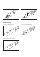
w w w.jbctools.com Desoldering Process When desoldering, use a tip with a diameter larger than the pad being desoldered. This will achieve maximum suction and thermal efficiency. OK 1. Apply the tip so that it fits over the component terminal. 2. When the solder liquefies, gently rotate the tip so that the terminal can be lifted off. 3. Then press the vacuum pump button long enough to suck up the solder. 003C360-003 360-006C360-006 The vacuum pump will continue to run for a few seconds.
B B 3. Insert the new heating element into the tool. 4. Tighten the fixing screw and insert the filter. A B Changing Iron Filter 1. Remove the tube from the filter. 3. Insert a new filter (ref. 0008473) into the tool and mount the tube onto the filter. 10 2. Remove the filter form the tool.
C360-004 C360-004 C360-006 C360-007 C360-007 C360-006 w w w.jbctools.com Cleaning Solder Collector Note: For this operations, turn off the station or disconnect the tool and wait until the tool temperature drops to room temperature. 1. Remove the filter before cleaning the solder collector. A B A 2. Take out the solder collector with the metal solder retention. B 3. Use the cleaning brush (ref. 0008297) to clean the solder collector inside or replace it for a new one. 4.
Electric Desoldering Module Note: Before carrying out maintenance, always unplug the equipment. If there is loss of suction, check that there is no obstruction in the tool (tip, heating element, tool filter), tube or suction filters. Changing Pump Filters Periodically check the filters and replace them if they are yellowish. Note: Do not use sharp pointed objects to open the suction filter. Suction Filter Ref. 0821830 Cotton Filters Ref. 0781046 O Ring Ref. 0007717 Filter Cover Ref.
w w w.jbctools.com Operation The JBC Most Efficient Soldering System This revolutionary technology is able to recover tip temperature extremely quickly. This allows the user to work at a lower temperature. As a result, tip life increases up to 5. 1. Work 2. Sleep 3. Hibernation Long time in the stand When the tool is lifted from the stand the tip will heat up to the selected temperature.
Control Process Work Screen Fixed temp. 3 5 0 o C The work screen provides useful information of tool status in real time. Earth Fuse warning is shown when fuse is blown. Replace the fuse. Levels ºC 2 7 0 3 5 0 4 0 0 350 0 c Displays a specific fixed temp. Shown when you have selected temp. levels. The values must be adjusted for the task. Selected temp. 3 5 0 o C EARTH FUSE -10 Power 5% “Temp. Adjust” parameter. It provides a more precise adjustment between the selected temp and the actual one.
w w w.jbctools.com Parameters Be careful when using these parameters as they may reduce the tip life if not used properly. Please follow the recommended guidelines: Station Settings Parameter Description Recommendations Temperature Unit Celsius (ºC) or Fahrenheit (ºF) N/a Maximum Temperature Set the maximum temperature to work with. Max. temp by default is 400°C (750°F). This is considered high enough to work with most lead-free applications.
Tool Settings Parameter Description Recommendations Warnings Fix One Temperature Fix a value within the temperature range of the station (90-450ºC/190-840ºF). Ideal for soldering more than one component at a specific temperature. The station will reject any attempt to change the temperature. N/a Temperature Levels Set Similar to “Fix one temp” parameter. In this case, the user can set up to 3 values for different power requirements. This allows a quick change between 3 different temperatures.
w w w.jbctools.com Tool Settings Parameter Description Recommendations Hibernation Delay Set the time the tool will remain at Sleep temperature before entering the Hibernation mode. At this time, the power supply is cut off and the tip remains at room temperature. This function completely protects the tip from oxidation during long periods of inactivity while the tool is in the stand. Retinning the tip before placing the tool in the stand also helps prevent oxidation and extends the life of the tip.
USB Connector Download the latest software from our website to improve your soldering station. JBC Updater www.jbctools.com/software.html Update the station software via USB connection: Cable USB AB JBC Updater JBC Web Manager www.jbctools.com/manager.html Manage and monitor as many stations as your PC can handle by using the JBC Web Manager. You can export data to another PC.
w w w.jbctools.com Maintenance Before carrying out maintenance, always switch the device off and disconnect it from the mains. Allow the equipment to cool down. Clean periodically Clean periodically - Clean the station screen with a glass cleaner or a damp cloth. - Use a damp cloth to clean the casing and the tool. Alcohol can only be used to clean the metal parts. - Periodically check that the metal parts of the tool and stand are clean so that the station can detect the tool status.
Safety It is imperative to follow safety guidelines to prevent electric shock, injury, fire or explosion. - Do not use the units for any purpose other than soldering or rework. Incorrect use may cause fire. - The power cord must be plugged into approved bases. Be sure that it is properly grounded before use. When unplugging it, hold the plug, not the wire. - Do not work on electrically live parts. - The tool should be placed in the stand when not in use in order to activate the sleep mode.
w w w.jbctools.
Notes 22
w w w.jbctools.com Specifications CS-1F 120V 50/60Hz. Input fuse: 2A. Output: 23.5V. Control Unit model: CSV-1F CS-2F 230V 50/60Hz. Input fuse: 1A. Output: 23.5V. Control Unit model: CSV-2F CS-9F 100V 50/60Hz. Input fuse: 2A. Output: 23.5V. Control Unit model: CSV-9F - Output Peak Power CS-F: - Temperature Range: - Idle Temp.
Warranty JBC’s 2 year warranty covers this equipment against all manufacturing defects, including the replacement of defective parts and labour. Warranty does not cover product wear or misuse. In order for the warranty to be valid, equipment must be returned, postage paid, to the dealer where it was purchased. Get 1 extra year JBC warranty by registering here: https://www.jbctools.com/productregistration/ within 30 days of purchase. www.jbctools.