
Owner's Manual

4
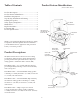
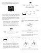
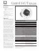
Step 1 – Cut the Hole. Cutout the circular hole to the cutout
hole size listed above. Pull the wiring through the cutout hole.
Figure 3:
Hole Cutout
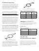
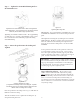
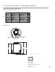
Step 2 – Insert Backing Hardware rough the Hole. Pack-
aged with the speakers are two types of backing hardware – a
C-shaped backing-plate bracket and two tile rails.
Suspended Ceilings – Insert the C-plate through the hole
cut in the ceiling tile. Place the C-plate around the hole with
the tabs located as shown on Figure 4. Insert the tile rails
through the cut hole in the ceiling tile. Snap the two rails
into the two tabs in the C-plate and align the rails so that the
ends extend OVER the T-channel grid on the side of the tile.
Secure the rails onto the C-bracket tabs by inserting a screw
though each tab into the rail. is can all be accomplished
from below the ceiling tile, if necessary.
FOR SAFETY:
IMPORTANT TO USE BRACKETS
ALL included support brackets – C-plate and
tile rails -- MUST be used when installing into
suspended ceiling tiles.
Figure 4:
C-Bracket and Tile Rail Positioning on Ceiling Tile
Additional Suspended Ceiling Installation
Information
Tile Rails: e tile rails are designed to t either standard
24-inch wide tiles or 600-mm wide tiles. e tile rail piec-
es do NOT physically attach to the T-grid struts. Instead,
the inverted-V shape at the ends of the rails sit OVER
the T-grid strut. During normal operation, the rails are
supported by the edge of the tile. If the tile were to come
out or fall apart, the ends of the support rails are designed
to catch onto the T-grid, providing secure support to hold
the loudspeaker assembly in place.
Vibration Reduction: Loudspeakers can generate sub-
stantial vibration which can cause buzzing of the ceiling
materials or structure. Depending on the character of the
ceiling tile and structure, the installer might need to place
neoprene or other dampening material under the tile rails
or the edges of the tiles to eliminate rattles.
Cutout Placement: e tile rails are pre-punched with
attachment holes along their length. Placement is not
limited to the center of the tile as is the case with many
other tile rail support systems.
Non-Suspended Ceiling Types – e C-bracket can be
optionally used by itself to shore up the ceiling material and
to spread out the clamping force from the tab clamps. Insert
the C-plate through the cut hole in the ceiling and place it on
the back side of the hole before inserting the speaker.
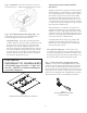
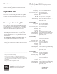
Step 3 – Connect the Wiring to the Removable Locking
Connector – e connector is INCLUDED with the speaker.
Connect the wire by stripping the insulation back about 5 mm
(about 3/16 inch). Do NOT strip wires back any longer than
this. Insert the bare end of wire fully into the connector (not al-
lowing any bare wire outside of connector) and screw down the
hold-down screw until tight using a small atblade screwdriver.
Tighten any unused screws to avoid rattling from vibration.
Figure 5:
Connecting Wires to Removeable
Locking Connector