
Owner's Manual

6
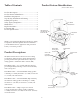
Step 6 – Tighten the Strain Relief Fitting & Close
the Terminal Cover
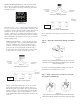
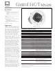
Figure 13:
Tighten the Two Horizontal Screws to Slide and Tighten the
Strain Relief Fitting. Then Tighten the Two Set Screws into the
Backcan. (Shown with a single speaker cable)
Tightening onto Flexible or Hard Conduit – e supplied tting
accommodates up to 3/8 inch (9.5mm) exible conduit. Insert
the conduit into the strain relief tting. Tighten the sliding
Strain Relief Fitting.
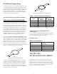
Step 7 – Insert the Speaker Into the Ceiling and
Tighten.
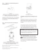
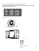
Figure 14:
Inserting Speaker into Ceiling
(C-ring/tile-rail assembly is above the ceiling tile. Speaker
inserted through cutout in ceiling material. Diagram shown
without cable and ceiling tile for clarity)
Insert the speaker into the ceiling as far as it goes, until the front
bae rim touches the ceiling.
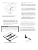
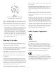
Turn the attachment screws to tighten the mounting tabs, by
using the following directions:
Figure 15:
Tightening Mounting Tabs
IMPORTANT -- For each attachment screw, FIRST turn ½ turn
COUNTER-CLOCKWISE to release the mounting tab from its
guide.
en tighten the mounting tabs by turning the screw CLOCK-
WISE until tight. e rst ¼ clockwise turn rotates the attach-
ment tabs outward and the remaining turns tighten the tabs
down onto the back of the ceiling surface. DO NOT OVER-
TIGHTEN.
A tab is provided on the back of each speaker for connection
to a independent secondary support point. Some construc-
tion codes require using this secondary support point, which
requires connecting a support line to a separate secure support
point. Consult construction codes in your region.
IMPORTANT -- Control Contractor ceiling speakers can gen-
erate substantial vibration . Using the seismic tab as a secondary
support point is highly recommended in case the ceiling tile
or structure breaks. In some areas, using the seismic tab as a
secondary support point is required by code.
Step 8 Adjust Tap Selector – e tap selector rotary
switch is located on the front bae. Adjust the tap setting
before applying power to the speaker and before inserting the
grille. From the OFF position, turn the selector counter-clock-
wise to set to the 8Ω (low impedance) nominal setting (see
spec sheet for more precise impedance information) or turn the
selector clockwise to set to the various 70V and 100V distribut-
ed system tap settings.