Control Contractor Ceiling Loudspeakers Control 24C/CT Micro and Control 24CT MicroPlus Owner's Manual
Table of Contents Product Description 2 Product Feature Identification 3 Installation Preparations 4 Step-By-Step Installation and Wiring 6 Painting the Speaker 11 Maintenance 12 Contacting JBL 14 Thank you for purchasing JBL Control Contractor ceiling loudspeakers. Read through this manual to familiarize yourself with the features, applications and precautions before you use these products.
Product Description The JBL Control Contractor ceiling loudspeakers utilize innovative design and materials to provide premium level performance from compact in-ceiling speakers. CONTROL 24C MICRO - Most compact of the JBL ceiling speakers, the Control 24C Micro contains a 4" woofer and a ¾" titanium-coated tweeter, providing high-fidelity sound over an extremely wide coverage area. The Control 24C Micro also has a small backcan and is ideal for smaller ceiling spaces.
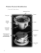
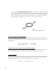
Product Feature Identification (Control 24CT Micro Shown) Attachment Screw Tweeter Tuning Port Rotating Mounting Tab Seismic Tab (Secondary Support) Attachment points for included or installer-provided strain-relief fittings.
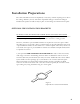
Installation Preparations The entire installation can be accomplished, if necessary, without requiring access above the ceiling. Bracketry for use with either suspended ceilings or sheetrock ceilings is included. The speaker is held securely in place via mounting ears which lock into place. OPTIONAL PRE-INSTALLATION BRACKETS IN MOST CASES, NO BRACKETS OTHER THAN THE ONES INCLUDED WITH YOUR SPEAKER ARE REQUIRED.
2. The optional PLASTER-RING BRACKET (or "mud ring") is identical to the New Construction Bracket, with the addition of a circular offset, forming an edge guide for sheet rock plastering. The bracket has wings that attach to the building structure. Sheet rock is typically either precut or cut with a rotary cutting tool. The sheet rock hole is then plastered (or "mudded") up to the ring to create a seamless cutout.
Step-by-Step Installation and Wiring The installation system has been designed so that the entire installation can be accomplished from beneath the ceiling, for instances when access above the tile is not possible or practical. However, in some cases it may be easier with removable ceiling tiles to access from both the top and bottom of the ceiling tile during various phases of the installation. Step 1 - Cut Ceiling Hole.
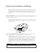
Figure 4: C-Bracket and Tile Rail Positioning on Ceiling Tile Tile Rails: The tile rails are designed to fit either standard 24-inch wide tiles or 600-mm wide tiles. The tile rail pieces do NOT physically attach to the T-grid struts. Instead, the inverted-V shape at the ends of the rails sit OVER the T-grid strut. During normal operation, the rails are supported by the edge of the tile.
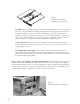
Guide to the Pins for Connection - The locking input connector contains 7 terminals, as marked above the connector. The pin functions are listed on the label located on the terminal cover plate. Control 24CT Micro: Hookup Chart 9W N.C. Control 24CT MicroPlus: 4W 9W 2W 4W 1W 2W 0.5W Com 1W Com 70V 100V Hookup Chart N.C. N.C. Control 24C Micro: N.C. 6W 12W 25W Com N.C. 12W 25W N.C.
1 - Cable Tie - If using loose wire, this cable tie can secure the loose ends of wire that are connected to the terminal block. The strap can be tightened by pulling on the loose end and then tightening the holding screw. Figure 7: Tightening the Cable Tie 2 - Adjustable Metal Strap - This adjustable steel tie fitting is provided for those applications where it can be utilized to affix a set of wires. It can be useful for regions where such a fitting is allowed for terminating a flexible conduit.
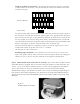
Step 5 - Insert the Speaker Into the Ceiling and Tighten. Insert the speaker into the ceiling as far as it goes, until the front baffle rim touches the ceiling. Turn the attachment screws to tighten the mounting tabs, by using the following directions: IMPORTANT - For each attachment screw, FIRST turn ½ turn COUNTER-CLOCKWISE to release the mounting tab from its guide. Figure 8: Inserting Speaker Into Ceiling Then tighten the mounting tabs by turning the screw CLOCKWISE until tight.
Painting the Speaker The speaker's textured white finish complements most decors and does not need further finishing. Where the interior design requires it, these speakers are easy to paint. The rim can be painted before installation or in cases where the rim needs to be finished along with the ceiling, the speaker rim can be painted after attaching into the ceiling. Type of Paint - The speaker's polystyrene rim accepts almost any type of latex or oil based paint. Two coats are recommended.
These products are in compliance with the EMC Directive 89/336/EEC and Article 10 (1) of the directive. In compliance with Technical Regulations EN50081-1 and EN50082-1. For a copy of the model-specific CE Declaration of Conformity, contact JBL at the address listed at the end of this manual. Maintenance No maintenance is required when installed in accordance with installation and wiring guidelines described in this manual.
13
Warranty & Contacting JBL These products are designed and backed by JBL Professional, the world leader in sound reinforcement. For complete JBL warranty information, to order replacement parts or to ask for clarifications to this manual, contact JBL Professional. WITHIN THE UNITED STATES: OUTSIDE OF THE USA: Applications Department, JBL Professional PO Box 2200, 8400 Balboa Blvd. Northridge, CA 91329 USA In the USA you may call Monday through Friday 8:00 am to 5:00 pm Pacific Coast Time (818) 894-8850.
JBL Professional 8500 Balboa Blvd, P.O. Box 2200 Northridge, CA 91329 U.S.A.
SPECSHEET Control® 24C/CT Micro Professional Series – Background Music Ceiling Speaker Key Features: • Extremely wide 150° coverage • Smooth frequency response • Components: • 4.5 inch (115 mm) woofer, injection molded graphite cone with butyl rubber surround • 0.
100 1000 10000 20000 Control® 24C/CT Micro Frequency (Hz) Professional Series – Background Music Ceiling Speaker 6.4 (163) Frequency Response: Horizontal Off Axis Frequency Response: -6 dB Beamwidth (degrees) 360 100 Horizontal Vertical Vertical Off Axis Frequency Response (up): 10 20 360 -6 dB Beamwidth (degrees) -6 dB Beamwidth (degrees) 100 1000 On axis in half-space (2pi, flush mounted in ceiling);10000 Frequency (Hz) thru (8W); input impedance (lower solid line) 20000 7.
SPECSHEET Control® 24C/CT Micro Professional Series – Background Music Ceiling Speaker Horizontal 1/3Horizontal Octave Polars 1/3 Octave Polars Horizontal 1/3 Octave Polars: Horizontal 1/3Horizontal Octave Polars 1/3 Octave Polars Architectural Specifications: The loudspeaker shall be of in-ceiling design, consisting of a 114 mm (4.5 in) low frequency transducer, a 12 mm (0.5 in) tweeter, and frequency dividing network installed in an integral ported enclosure.
SPECSHEET Control® 24C/CT Micro Professional Series – Background Music Ceiling Speaker Vertical 1/3 Octave VerticalPolars 1/3 Octave Polars Vertical 1/3 Octave Polars: © 2019 Harman International. www.jblpro.