
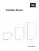
Specifications


4
BEFORE INSTALLING SPEAKERS
• Conceal series loudspeakers require a stable mounting structure for proper support. Speakers should only be attached
to non-moveable elements of a building such as a structural ceiling or structural wall and must allow for screw
attachment of all four sides of the speaker and the adjoining wallboard. Well-cured and dry structural pine 2" × 4"
studs (35 × 70 mm) can be used for such framing if the existing construction does not provide the required stable
mounting structure. If the stable mounting structure is in a lowered ceiling, then you must use ceiling hangers to directly
secure the mounting structure to the building structural ceiling. Mount the speaker to the stable mounting structure per
Conceal series speaker installation instructions.
• Do not install Conceal series speakers before the wallboard is hung, instead install a pre-construction board (PCB)
where each speaker will be located. Exposing speakers to the construction environment during the installation of
wallboard runs the risk of damage and improper alignment with the surrounding wallboard.
SPEAKER WIRING
• JBL recommends using 16 gauge AWG speaker wire for runs of less than 100 ft (30.5 m) and 14 gauge AWG speaker
wire for runs of 100 ft to 250 ft (30.5 m - 76 m).
• Attach speaker wiring securely to the studs. Make sure to properly connect the speaker wires to the speaker binding
posts; jiggle the wires and re-tighten.
SPEAKER INSTALLATION: RETROFIT
• Installing a Conceal Invisible Loudspeaker into an existing nished wall is similar to making a wallboard patch.
• Remove the overlay sheet that comes attached to the front of each speaker and temporarily attach them to the walls to
assist in planning speaker placement and for tracing the cutout opening.
• Once the approximate speaker locations have been selected, use a stud nder to locate the framing and drill test holes
to verify. Align the edges of the overlay sheet so they are centered on the framing. Cut the wallboard to the size of the
speaker using the overlay. The nished opening should be 16” wide and centered on the framing studs.
• Proceed to Installation Step 2 "Speaker Alignment and Test Fit".
SPEAKER INSTALLATION: NEW CONSTRUCTION
1. Framing & Pre-construction Brackets (PCB)
• For retrofits and for new construction, it is recommended to add cross member framing above and below the
speaker opening so that the speaker may be attached on all four sides.
• In new construction, pre-construction brackets (PCB) should be installed when the job is pre-wired. Center the
PCB on the framing and attach with provided hardware. This reserves the exact space for the speaker during the
wallboard installation preventing the speaker panel itself from exposure to harsh construction environment and
also force the wallboard installers to hang the wallboard around the PCB leaving a perfectly sized opening for the
speaker.
2. Speaker Alignment and Test Fit
• After the wallboard has been installed, remove the pre-construction board (PCB).
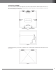
• Before seam finishing occurs, it is critical to test fit each speaker to check its registration with the surrounding
wallboard. For correct registration, the perimeter screw flange of the speaker panel should be flush with the
adjoining wallboard (See Figure 4). This creates a recess for seam tape to prevent sanding back into the tape
during the nishing process.
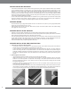
• If necessary, attach the provided self-adhesive shims to the rear of the speaker. Place the shims over the screw
holes and leave no gaps (See Figure 5).
• It is critical to add the correct number of shims so that the wallboard and ange surfaces are ush with one another.
If the speaker is recessed in relation to the wallboard excessive material build-up on the surface of the speaker can
occur during the nishing process which may lead to poor sound quality and possible premature failure.
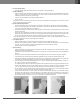
Figure 4 Figure 5 Figure 6