
Portable Speaker User Manual


6
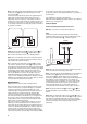
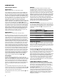
Step 3. Connect the speaker wire (included) to the push terminals on
the active speaker
and the push terminals on the rear of the
passive speaker
.
See Figure 3. Please note that the speaker wire supplied features a
polarity stripe to help distinguish its two conductors. Use this
polarity stripe to ensure that you are connecting the positive (+)
terminal on one speaker to the positive (+) terminal on the other, and
the negative (–) to the negative (–). It does not matter whether you
use the striped conductor for connecting the positive (+) terminals or
the negative (–) terminals.
Figure 3.
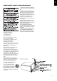
Step 4. Plug the transmitter module
and active speaker
into
the wall outlet, using the correct power supply and power cord.
Make sure the transmitter’s antenna
is extended upwards.
Step 5. If necessary, configure your source to activate the preamp
level outputs for the surround/rear channels (consult your source’s
owner’s manual for specific instructions).
Make sure the ID code setting on the transmitter
is set to the
same setting as that on the active speaker
. See Page 8 of this
manual for more information on ID codes. When connected properly,
the top LED on the front of the active speaker should be green. When
first plugged in, it will sometimes take several seconds for the
Control 2.4G AW active speaker to initialize and “wake up.“ Until
then, the top LED will be in red. Once the top LED is green, the
bottom LED should flash green until the transmitter and active
speaker “lock in.” It will then also illuminate in solid green. This LED
will light in orange if the local input on the active speaker is selected
(see Page 8 under Local Input for more details).
Application 2
Adding speakers to remote locations around your home:
Audio sources that can be used in this application may be an A/V
receiver or audio receiver, a portable audio player, or a computer
featuring a sound card. First, determine whether your source
contains RCA-type preamp outputs for the front/main channels or a
3,5mm (1/8-inch) stereo single-pin output. On an A/V or audio
receiver, the preamp outputs are usually indicated by RCA-type
jacks on the back of the receiver labeled as “pre-out” (please refer
to your source’s owner’s manual to confirm whether it includes
preamp outputs). If your source includes these RCA-type outputs,
follow the steps in Connection Option A.
If your source features a 3,5 mm (1/8-inch) single-pin stereo jack,
follow steps in Connection Option B. If your receiver does not
feature either type of preamp outputs for the front/main channels, it
cannot be used with Control 2.4G AW. Some computer sound cards
feature more than one 3,5 mm(1/8-inch) single-pin jack. There is
almost always one output that is called a speaker output. However,
some sound cards feature a preamp output or line output in addition
to or instead of speaker outputs. If your computer does feature
preamp or line outputs, we recommend that they be used instead of
speaker outputs.
If you would like to connect the computer to the
JBL On Air Control 2.4G AW using preamp outputs on your computer,
follow the steps in Connection A.
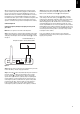
Connection Option A
Connecting using the preamp outputs on your source:
Note: Make sure power is turned off on all components.
Step 1.
Connect the interconnect cable (included) to the left and right
front/main preamp outputs or zone 2 outputs or REC outputs and the
inputs on the transmitter module
, as shown in Figure 4.
Figure 4.
Step 2. Place the active speaker in the desired location in your home
near an AC outlet, as it needs to plug in to the wall.
Step 3. Connect the speaker wire (included) to the push terminals on
the active speaker
and the push terminals on the rear of the
passive speaker
, as shown in Figure 3. Please note that the
speaker wire supplied features a polarity stripe to help distinguish its
two conductors. Use this polarity stripe to ensure that you are
connecting the positive (+) terminal on one speaker to the positive
(+) terminal on the other, and the negative (–) to the negative (–).
It does not matter whether you use the striped conductor for
connecting the positive (+) terminals or the negative (–) terminals.
Step 4. Plug the transmitter module
and active speaker
into
the wall outlet. Make sure the transmitter’s antenna
is extended
upward.
Step 5. Make sure the ID code setting on the transmitter
is set to
the same setting as that on the active speaker
. See Page 8 of this
manual for more information on ID codes. If necessary, configure
your receiver to activate the preamp level outputs for the main/front
channels (consult your source’s owner’s manual for specific
instructions).
INPUT
RL
R
L
ID
CODE
1234
Front/Main/Second Room
Preamp Outputs
SOURCE
ID
CODE
1234
DC 20V
SUB OUT LINE IN
LEFT CHANNEL SPEAKER
TO RIGHT SPEAKER
+–
RIGHT CHANNEL SPEAKER
TO LEFT SPEAKER
+–
0039CSK JBL On Air Control_2.4_AW_ENG_v5_GODKENDT:34199_Control_2_4G_Eng 10/06/08 15:57 Side 6