3 0 0 S e r i e s C o n t r o l 3 21C / C T User’s Guide Control 322C/CT Control 328C/CT C o n t r o l 312 C S
TABLE OF CONTENTS Product Description 3 Product Feature Identification 4 Wiring Instructions 5 Control 328C/CT System Assembly 7 Control 321C/CT, Control 322C/CT & Control 312CS System Assembly 8 Painting the Grille 10 Maintenance 10 Accessories 10 Contacting JBL Professional 10 Specifications 11 JBL Professional Control 300 Series
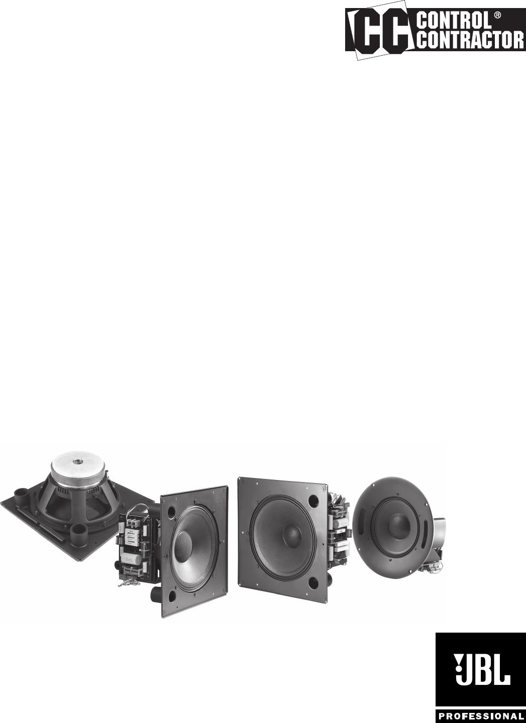
PRODUCT DESCRIPTION JBL Professional Control® 300 Large Format, In-Ceiling Loudspeakers are designed from the ground up to provide optimal performance for the most demanding installed sound applications. Thanks to the conical constant coverage waveguide design, Control 300 Series Loudspeakers feature exceptional broadband control ensuring extremely even coverage and remarkably consistent performance.
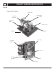
PRODUCT FEATURE IDENTIFICATION (Control 322CT Shown) Transformer Crossover Network Compression Driver Tuning Port Tube Woofer Frame Baffle EZ-Rail™ Crossover Network Dust Cap Woofer Tuning Port Tube Baffle Tuning Port 4 JBL Professional Control 300 Series
WIRING INSTRUCTIONS Control 300 Series Loudspeakers include Euroblock or Phoenix-type locking input connectors that allow the system to be “pre-wired” before the speakers are installed into their respective back cans and backboxes.
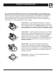
WIRING INSTRUCTIONS Figure B: Parallel System Hookup Diagram + Power Amp + - 1 2 3 4 1 2 3 4 1 2 3 4 Speaker 1 Speaker 2 Speaker 3 - 2.) Using Loop-Through Terminals (Pins 2 & 3) -- By connecting the wire pair of the subsequent speaker to pins 2 & 3, then all subsequent speakers will be disconnected when this speaker’s connector is disconnected during troubleshooting .
CONTROL 328C/CT SYSTEM ASSEMBLY Ceiling Preparation - Cut a 12.2 inch (310 mm) diameter hole in the ceiling to allow sufficient room for the loudspeaker baffle. Assembling the Control 328C/CT into the Back Can - After inserting the Control 328C/CT into the back can, align the mouting holes without weld nuts to the holes with clip nuts on the back can. These are the mounting points that will be used to secure the Control 328 baffle and driver to the backcan.
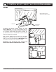
CONTROL 321C/CT, 322C/CT & 312CS SYSTEM ASSEMBLY MTC-300BB12 Back Box Shown as Cut-Away for Clarity Loudspeaker Assembling the Control 321C/CT, 322C/CT or 312CS into the Back Box - First, line up the EZ-Rail™ with one of the back box flanges containing a singular mounting hole. For orientation when holding the speaker overhead, two (2) embossed arrows on the underside of the metal baffle indicate the edge with the EZ-Rail.
CONTROL 321C/CT, 322C/CT & 312CS SYSTEM ASSEMBLY Ceiling Preparation - Cut a 14.9 x 14.9 inch (378 x 378 mm) hole in the ceiling to allow sufficient room for the loudspeaker baffle. Using JBL Professional’s MTC-300BB12 Back Box -- The MTC-300BB12 is compatible with two common mounting systems for installing the loudspeaker / baffle to the back box; either of these mounting systems may be utilized. Screws are included with the MTC-300BB12 Back Box.
ACCESSORIES, MAINTENANCE & CONTACTING JBL Painting the Grille -- Control 300 Series Grilles feature a powder coated, satin finish paint (RAL 9016 - Pantone equivalent 11-0602TPX) and can be painted to match any decor. This should only be done when the grilles have been removed from their loudspeaker and back box / can assembly. Contacting JBL Professional -- These products are designed and backed by JBL Professional, the world leader in professional sound reinforcement.
SPECIFICATIONS Control 328C/CT Frequency Range (-10 dB)1: 45 Hz – 18 kHz Frequency Response (±3 dB)1: 60 Hz – 16 kHz Coverage Pattern2: 120º conical, broadband (Avg 1k - 16kHz) Long-Term System Power Rating, IEC3: 250 W (1600 W peak), 2 hrs 150 W (1000 W peak), 100 hrs Sensitivity (2.83V@ 1m): 93 dB4 measured half-space Nominal Impedance : 8 ohms (328C) Transformer Taps : 100V: 68W, 34W & 17W (plus 8.
3 0 0 363816-001 S e r i e s 8500 Balboa Boulevard Northridge, CA 91329 USA Visit us online at www.jblpro.