
Owner's Manual
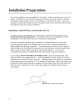
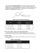

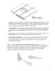


Table Of Contents

8
Guide to the Pins for Connection --
The removable locking input connector contains 4
terminals,
as
marked
on
the connector. The
pin
functions are listed
on
the label located
on
the terminal cover plate.
Figure 6: Connector Pins
Pins 2 & 3 are
the"+"
and"-"
inputs
to
the loudspeaker. Pins 2 & 3 are looped to pins 1
&
4,
respectively (Pin 1 connects
to
Pin
2
and
Pin
3 connects to
Pin
4) inside
the
speaker.
Pins 1 & 4 are intended
as
loop-through connections to subsequent loudspeakers. There
are
two
possible hookup schemes for connecting subsequent speakers, determined
by
the
desired result from the circuit whenever this
speaker's
connector gets disconnected during
troubleshooting:
Paralleling Input Terminals
--Connect
the
wire pair
of
the subsequent speaker to
pins 2 & 3 (in parallel
with
the input wire pair). Whenev
er
the connector is pulled out
of
the speaker for troubleshooting, subsequent speakers will stay connected. This can
be
useful during troubleshooting to
be
able to disconnect a single loudspeaker at a time.
In this hookup scheme,
no
wires get connected to pins 1 & 4.
Figure
7:
Paralleling Input Terminals
Figure 8:
From
Amplifier
or
Previous
Speaker
Parallel
System
Hookup Diagram
II
~~
+
To
Subsequent
Speakers
,------.
,....------,
.--------,
,---------<+-
To
+ -
Pow
er
Amp
lifier
Speak
er
1
Speaker 2
Soeaker 3
Subseque
nt
Speakers