
User Manual


10
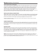
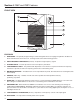
REAR PANEL
11. VENTILATION SLOTS - These slots provide air ow to reduce heat inside the enclosure, this ensure that
airow is not impeded.
12. LCD DISPLAY – Text in the display indicates status of software-controlled settings.
13. BACK KEY – Press this key to return to prior display screen.
14. ENTER KEY – Press this button to select and enable the value displayed on the screen.
15. HiQnet™ PORT – This port allows feature updates as they become available
16. POWER SWITCH – Press "I" to apply power and "O" to disable power.
17. IEC POWER CONNECTOR – This connector supplies power to the speaker’s electronics. Connect the
supplied IEC Grounded Power Cord to this connector.
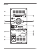
18. FRONT PANEL INDICATORS – This chart illustrates status of functions as indicated by the
Front Panel LEDs.
• Locate – Flashing WHITE LED is used to selectively identify the speaker when connected to a
HiQnet™ network.
• Power – A persistent WHITE LED indicates the unit is powered on.
• Limit – A ashing RED LED indicates protective limiting is engaged.
• Error – Persistent RED LED – indicates a system fault or when using digital input, interruption of loss of
valid digital word clock.
• User Settings – Persistent GREEN LED indicates EQ, Delay and other processing are enabled.
19. MENU KEY – Press this key to access a directory of software-enabled features.
20. ROTARY CONTROL – Rotate this dial to review menu options.
21. ANALOG INPUT – An XLR Female connector is used to connect balanced and unbalanced analog equipment.
22. DIGITAL INPUT – An XLR Female connector is used to connect AES3 format digital signals.
23. DIGITAL THROUGH – Use this output connector to route the incoming AES3 signal to another speaker.