Contro l ® 47C / T Contro l ® 47LP Contro l ® 47H C User’s Guide Control® 45C/ T Control® 42C Control® 40CS/ T Rev D
TABLE OF CONTENTS Product Description .....................................................1 Product Feature Identification ..................................2 Control 40 Series Preparation ...................................3 Control 40 Series Installation ....................................4 Wiring Instructions ...................................................5-6 Grilles, Maintenance & Contacting JBL ..................7 Specifications ...........................................................
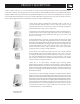
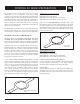
PRODUCT DESCRIPTION Control® Contractor 40 Series is a line of premium, in-ceiling, specialty loudspeakers that combine outstanding pattern control and consistent coverage with superior sonic performance. Featuring JBL’s proprietary conical Radiation Boundary Integrator® (RBI™) technology, adapted from the groundbreaking VerTec® Series of line array loudspeakers, the Control 40 series includes five models.
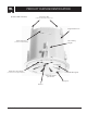
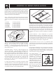
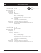
PRODUCT FEATURE IDENTIFICATION (Control 47C/T Shown) Suspension Tabs (Control 47C/T & 47HC models only) Integrated Back Can Input Connectors Two-Landing Dog Ear (located inside terminal well) Transformer Tap / Bypass (located inside waveguide aperture) Conical RBI® Waveguide Shown with included grille removed.
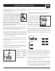
CONTROL 40 SERIES PREPARATION The installation of the Control Contractor 40 Series in-ceiling loudspeakers can be accomplished, if necessary, without requiring access above the ceiling. Bracketry for use with either suspended ceilings or sheetrock ceilings is included (see below for additional details on the Control 42C). The loudspeaker is held securely in place via mounting ears which lock into place.
CONTROL 40 SERIES INSTALLATION The installation system has been designed so that the entire installation can be accomplished from beneath the ceiling, for instances when access above the tile is not possible or practical. However, in some cases it may be easier with removable ceiling tiles to access from both the top and bottom of the ceiling tile during various phases of the installation. Step 1 – Cut the Hole.
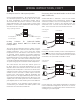
WIRING INSTRUCTIONS Control Contractor 40 Series in-ceiling loudspeakers include Euroblock locking input connectors that allow the system to be “pre-wired”. Connecting the Wiring to the Euroblock -- Connect the wiring to the removable locking connector that is INCLUDED with the speaker by stripping the insulation + back about 5 mm (about 3/16 inch), inserting the bare end of wire into the connector and screwing down the holddown screw until tight using a small flatblade screwdriver.
WIRING INSTRUCTIONS, CON’T Hookup Schemes for Subsequent Speakers Using Loop-Through Terminals -- By connecting the wire pair of a subsequent speakers to the “Loop Thru” on the Control 40 Series Loudspeakers all subsequent speakers will be disconnected when this speaker’s connector is disconnected during troubleshooting. This can be useful as a way to isolate problems to a section of the distributed line while leaving the wires attached to the connector.
PAINTING & CONTACTING JBL PAINTING CONTROL CONTRACTOR 40 SERIES LOUDSPEAKERS The trim ring and grille of Control Contractor 40 Series loudspeakers can be painted to match almost any decor. The speaker’s polystyrene rim accepts almost any type of latex or oil based paint. Maintenance -- No maintenance is required when assembled in accordance with the instructions and wiring guidelines described in this manual. CONTACTING JBL PROFESSIONAL For best results, the following procedure is recommended: 1.
SPECIFICATIONS Control 47C/T: Frequency Range (-10 dB)1: 55 Hz - 20 kHz Frequency Response (± 3 dB)1: 75 Hz - 17 kHz Power Capacity2: 150 Watts Continuous Program Power 75 Watts Continuous Pink Noise Nominal Sensitivity (2.83V/1m)1: 91 dB Nominal Coverage Angle3: 120° conical coverage Directivity Factor (Q)3: 6.5 Directivity Index (DI)3: 7.9dB Rated Maximum SPL: 110 dB @ 1 m (3.3 ft) average, 116 dB peak Rated Impedance: 8 Ω (in bypass mode) Transformer Taps: 60W 30W, 15W, (& 7.
SPECIFICATIONS Control 47HC: Frequency Range (-10 dB)1: 55 Hz - 17 kHz Frequency Response (± 3 dB)1: 70 Hz - 14 kHz Power Capacity2: 150 Watts Continuous Program Power 75 Watts Continuous Pink Noise Nominal Sensitivity (2.83V/1m)1: 93 dB Nominal Coverage Angle3: 75° conical coverage Directivity Factor (Q)3: 10.2 Directivity Index (DI)3: 12.0dB Rated Maximum SPL: 112 dB @ 1 m (3.3 ft) average, 114 dB peak Rated Impedance: 6.6Ω (in bypass mode) Transformer Taps: 60W 30W, 15W, (& 7.
SPECIFICATIONS Control 42C: Frequency Range (-10 dB)1: 140 Hz - 20 kHz Frequency Response (± 3 dB)1: 180 Hz - 17 kHz Power Capacity2: 30 Watts Continuous Program Power 15 Watts Continuous Pink Noise Nominal Sensitivity (2.83V/1m)1: 82 dB Nominal Coverage Angle3: 160° conical coverage Directivity Factor (Q)3: 6.6 Directivity Index (DI)3: 6.8dB Rated Maximum SPL: 94 dB @ 1 m (3.3 ft) average, 100 dB peak Rated Impedance: 16Ω Driver: 60mm (2.