GTH400-20107 06/03/98 15:49 Side 26
GTH400-20107 06/03/98 15:49 Side 1 GTH400 GTH400 6/5/4/3 CHANNEL AUTOMOTIVE POWER AMPLIFIER OWNER’S MANUAL
GTH400-20107 06/03/98 15:49 Side 2 Table of Contents 1. Introduction...................................................................................... 3 1.1 Features .................................................................................... 4 1.2 About Installation ...................................................................... 4 2. Installation and use .......................................................................... 5 3. System Design with the GTH400.......................
GTH400-20107 06/03/98 15:49 Side 3 1. Introduction Thanks for purchasing your new GT series automotive multichannel amplifier. Your GT series amplifier will easily connect to virtually any car audio system, whether it is factory installed or one purchased separately. The GTH400 includes an abundance of unique features which are described in this manual. The most obvious feature of the GTH400 is its 6-channel, staggered-power design.
GTH400-20107 06/03/98 15:49 Side 4 1.1 Features 1.2 About Installation Theory of Operation – Virtual Center Image Enhancer Although the GTH400 is designed to make installation as easy as possible, it is an extremely sophisticated product that requires proper installation and setup to realize its full performance potential. If you feel you do not have the necessary knowledge and skills, we strongly recommend that the installation be done by your authorized JBL dealer.
GTH400-20107 06/03/98 15:49 Side 5 2. Installation and use Refer to the “Crossover Frequency Adjustments” and “Speaker-Level Input Impedance Adjustments” sections of this manual to see if you will need to make alterations to their factory settings. 1. Disconnect the negative cable from the battery. Note: If the vehicle’s radio features a code type security system, make certain you know the code before disconnecting the battery! 2.
GTH400-20107 06/03/98 15:49 Side 6 3. System Design Using the GTH400 3.1 Speaker Requirements When used in the non-bridged mode a group-channel of the GTH400 can easily drive two 2-ohm speaker loads. When only one speaker is connected to the left and right outputs of a group, virtually any conventional speaker may be used. When two speakers are connected in parallel to a single output (left or right) of a given group, each speaker must have a minimum impedance of at least 4 ohms.
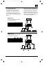
GTH400-20107 06/03/98 15:49 Side 7 The GTH400 uses the terminology “Group 1,” “Group 2” and “Group 3” to indicate the three main signal paths within the amplifier. Each “group” may consist of a mono bridged signal or a stereo pair of L+R signals depending on the system configuration. 3.2 Typical Applications The diagrams on pages 8 & 9 show the most common basic system configurations of the GTH400. One or more of these building blocks may be combined to form elaborate system designs.
GTH400-20107 06/03/98 15:49 Side 8 Application 3 4-Channel Full-Range or Bi-Amplified L Input Mode Group 2 Input Group 3 Input Speaker Crossover Preamp Output Crossover Group 1 L – – Flat – Group 2 L GR 2 – Flat – Group 3 Stereo – GR 3 Flat – Group 1 L – – High Pass – L R Rear L R L GR 1 GR 3 GR 2 GTH400 4-Channel Bi-Amplified with Fading Mono Subwoofers Input Mode Group 2 Input Group 3 Input Speaker Crossover Preamp Crossover R Preamp or Speaker-Level Input Front L 4-Channel Full-Range
GTH400-20107 06/03/98 15:49 Side 9 4. Installation and Use 4.1 Controls and Connectors 1. Preamp-Level Input Connector – Use these connectors for line (preamp) level inputs to the amplifier. 2. Preamp-Level Output Connector – Use these outputs to send signal to additional amplifiers. 3. Speaker-Level Input Connector – Use this connector for speaker level input signals. A wire harness is supplied for use with this connector. See “Audio Input Connections” section (page 23) for wiring instructions.
GTH400-20107 06/03/98 15:49 Side 10 to use in conjunction with a highpass filtered input signal to create a bandpass crossover (for a midrange or midbass driver). Set the switch to H (high) to activate the high-pass filter for use with satellite speakers or tweeters on an amplifier group. 13. Mode Switches – These switches are used to set the input mode for both preamp and speaker-level inputs. Set the switch to ST(ereo) for normal operation on the group using individual left and right inputs.
GR 2 GR 1 GR 3 GR 2 GR 1 R L R L - + - + - + - + Speaker-level inputs R L R L R L Buffer Buffer Buffer Buffer Buffer Buffer Buffer Buffer Buffer Buffer + + ∑ + ∑ + ∑ ∑ + CH. 1 L IN CH. 1 R IN + ∑ + ∑ + GROUP 2 INPUT 1 – GR 1 2 – GR 2 2 1 2 1 CH. 2 R IN 1 2 3 1 2 3 CH.
GTH400-20107 06/03/98 15:49 Side 12 rotary-type control, not one controlled by electronic pushbuttons. 4.2 Internal Adjustments Speaker-Level Input Impedance Adjustments The speaker level inputs of the GTH400 come factory set with 100k ohm input impedance. This will provide the lowest distortion operation from the speaker outputs of most modern head units by reducing the power the amplifier in the head unit must deliver to practically nothing.
GTH400-20107 06/03/98 15:49 Side 13 Custom Chip Construction Regardless of whether you build or buy it, the necessary resistor network has the following configuration: •Each resistor in the package has the same value. 1. Remove the screws from the bottom panel as shown below. 2. Select which resistor module, high pass or low pass, that you wish to change. 3. A chip puller, which can be obtained from any electronics store, is recommended to remove the resistor chip.
Side 14 14 – Rear Speakers + R + – L – Subwoofers L – The right and left inputs and outputs of the GTH400 must be reversed for proper functioning of the virtual center image enhancer when used in a right hand drive automobile. + – R + R+ L– L+ R– R+ L– GR 2 Group 2 R– Group 1 L R L+ Front L R L– Rear GR 1 L+ L GTH400 Front Speakers + – R + GTH400 Audio Signal Connection for Right Hand Drive Cars GR 3 1.
GTH400-20107 06/03/98 15:49 Side 15 FACE PLATE DASH PANEL FACE PLATE SPACER PLATE (INCLUDED) Cassette/CD Tuner Speaker Level Output Connection (Use only when line level ouput is not available) CD Player or Changer Cassette/CD Tuner Antenna Input Power Antenna Amplifier Speaker Level Inputs Fuse Fuse Amplifier Power Connection Amplifier Speaker Output Connection Red - Main +12V Yellow - Back Up Power Remote On/Off Black - Power Ground Cassette/CD Preamp Output Remote Antenna Blue (Blue/Wh
GTH400-20107 06/03/98 15:49 Side 16 insulated crimp-on connector or secure set-screw-type terminal blocks. Never leave bare wire exposed. Terminate wires with crimpor solder-on lug terminals whenever appropriate. is heat- and oil-resistant whenever running wires through the engine compartment. All wire-to-wire connections should be soldered and insulated with heat shrink tubing, or connected through a high-quality Simultaneous Stereo-Mono Connection Diagrams Subwoofer (Low-Pass) A.
GTH400-20107 06/03/98 15:49 Side 17 •The GTH400 will draw as much as 60 amps from the vehicle’s electrical system, enough to overload conventional vehicle wiring. Therefore the +12 volt power supply must be taken directly from the positive side of the battery. Do not connect to the vehicle’s fuse block or to a wire feeding other accessories.
GTH400-20107 06/03/98 15:49 Side 18 background noise levels in the system low. •To adjust a system using a single GTH400, start with all three of the amplifier gain controls fully counterclockwise and the Imaging Enhancer Remote set to “Bypass” mode. Some head units have additional output level controls or switches. Set those to their maximum position. •Set the level controls on any associated equipment such as equalizers and electronic crossovers as recommended by their manufacturers.
GTH400-20107 06/03/98 15:50 Side 19 position for driver-optimized sound stage. 5. Proceed to push and pull the RearAmbience knob to hear the effects of “Driver” and “All” modes. You should hear imaging coming from the middle of the dashboard when the knob is pushed in (“Driver” mode). You should hear stereo with ambience recovery when the knob is pulled out (“All” mode).
GTH400-20107 06/03/98 15:50 Side 20 and off, or does not work at all, a problem in installation or an abnormal electrical condition is indicated. Check speaker wiring for short circuits or impedance loads significantly below 2 ohms (4 ohms in bridged mode). Check the power supply voltage at the input of the amplifier to be sure that it is normal; between 11 and 16 volts. Check that the power wires are not reversed.
GTH400-20107 06/03/98 15:50 Side 21 7. In Case of Difficulty Power-on light does not come on • Head unit not on; turn the head unit on. • Ground wire is disconnected or defective; check for continuity with an ohmmeter between the amplifier’s ground terminal and a known chassis ground point. • Battery wire is disconnected or defective; check for approximately +12 volts between the amplifier’s battery and ground terminals.
GTH400-20107 06/03/98 15:50 Side 22 Power light is on, but no sound is heard from some or all of the speakers • Defective head unit or signal processor; check each component for proper wiring and operation. • Defective GTH400; If there is audio signal present at the inputs of the amplifier and there is no output, the GTH400 may be defective. Alternator whine through the audio system • Ground loops; follow the wiring with the engine running suggestions in the section called “Solving Noise Problems.
GTH400-20107 06/03/98 15:50 Side 23 8. Specifications GTH400 35 Watts x 4 + 70 Watts x 2 (4 ohms, 0.05% THD) 50 Watts x 4 + 100 Watts x 2 (2 ohms, 0.08% THD) 100 Watts x 2 (Bridged 4 ohms, 0.08% THD) + 70 Watts x 2 (4 ohms, 0.05% THD) 100 Watts x 2 (Bridged 4 ohms, 0.08% THD) + 200 Watts x 1 (Bridged 4 ohms, at 0.08% THD) Signal to Noise Ratio 100dBA Frequency Response 10Hz – 50kHz (+0, –1dB) 20Hz – 20kHz (+0, –0.
GTH400-20107 06/03/98 15:50 Side 24 Power Requirement 11 to 16V DC Negative Ground Fuse Size 30 Amp ATC Type Fuse (2 per Amplifier) Size (L x W x H) 15-1/4" x 11-1/4" x 2" (387mm x 286mm x 51mm) Weight 13 lbs 4 oz (6 kg) Speaker Level Input Molex Mini-Fit Jr Mating Connector #39-01-2080 Metal Pins: 39-00-0038 Remote Control Drilling Template 9/64" (3.5mm) in 4 places 9/64" (3.
GTH400-20107 06/03/98 15:50 Side 25 Staple or clip your original bill of sale here.