
Car Amplifier User Manual


9
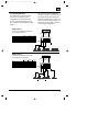
4. Installation and Use
4.1 Controls and Connectors
1. Preamp-Level Input Connector –
Use these connectors for line (pre-
amp) level inputs to the amplifier.
2. Preamp-Level Output Connector –
Use these outputs to send
signal to additional amplifiers.
3. Speaker-Level Input Connector –
Use this connector for speaker level
input signals. A wire harness is
supplied for use with this
connector. See “Audio Input
Connections” section (page 23) for
wiring instructions. This input also
includes JBL’s Common Sense
input circuitry which turns the
amplifier on as soon as the high
powered head unit connected to
this input is turned on.
4. Speaker Output Connectors –
Connect speaker wiring to these
connectors. See wiring directions
for more information.
5., 6., 7., 8. Power Connector –
Connection for power wires. See
wiring directions for information on
proper connections.
9. Fuses – Two 30 Amp ATC type
fuses.
10. Gain Controls – Use these controls
to adjust the gain of the amplifier
channel group. See the “Adjusting
the Gain” section (on page 25) for
tips on proper setup.
11. Preamp Crossover Switches – These
switches control the built-in cross-
overs that are directed to the
preamp-output connectors. Set the
switch to F (flat) for full-band
operation for that group. Set the
switch to L (low) to activate the low-
pass filter on the pre-amp output
group (for subwoofer use or to use
in conjunction with a high-pass
filtered input signal to create a
bandpass crossover for a midrange
or midbass driver). Set the switch to
High-Pass to activate the high-pass
filter for use with satellite speakers
or tweeters on the pre-amp output
group.
12. Speaker Crossover Switches –
These switches control the built-in
crossovers that are connected to
each group's power amplifier cir-
cuitry. Set the switch to F (flat) for
full band operation on a group. Set
this switch to L (low) to activate
the
low-pass filter on the selected
amplifier group for subwoofer use or
GTH400-20107 06/03/98 15:49 Side 9