Models: ™ Northridge E-Series E250P Performance Series P12SW Powered Subwoofers Service Manual JBL Consumer Products 250 Crossways Park Dr.
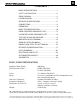
E250P/P12SW subwoofers - CONTENTS BASIC SPECIFICATIONS …………….……..…………..1 SAFETY INFORMATION …………….……..….………..2 E250P PACKING……..………………….….….….……...3 P12SW PACKING……..……………………….…………4 DETAILED SPECIFICATIONS ……….……..…………..5 CONNECTIONS………………………...……..…...…..…6 OPERATION ……..………………….……...…….….…...9 BASIC TROUBLESHOOTING…………………………..10 E250P EXPLODED VIEW/PARTS LIST……………….11 P12SW EXPLODED VIEW/PARTS LIST……….……..12 TEST SET-UP AND PROCEDURE….
E250P/P12SW subwoofers SAFETY INFORMATION Warning List of Safety Components Requiring Exact Replacements Any person performing service of this unit will be exposed to hazardous voltages and the risk of electric shock. It is assumed that any person who removes the amplifier from this cabinet has been properly trained in protecting against avoidable injury and shock.
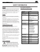
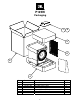
E250P Packaging 1 5 3 14 2 4 Ref# Part Number Description 1 2 351249-002 351249-001 351249-003 350884-003 351252-001 351252-002 338381-001 352024-001 MANUAL, OWNER-E250P/E250P CARTON,MASTER-E250P (BEECH MODEL) CARTON,MASTER-E250P (BLACK MODEL) CARTON,MASTER-E250P (CHERRY MODEL) PAD,END,TOP-E250P PAD,END,BOT-E250P WARRANTY CARD,1/5YR,JBL ASY, GRILLE, BLK, FRNT 3 4 5 14 Qty 3 1 1 1 1 1 1 1 1
P12SW Packaging 1 5 3 6 2 4 Ref# Part Number Description 1 2 3 4 5 6 361803-001 361813-001 351252-001 351252-002 338381-001 352024-003 P12SW Owner’s Manual P12SW Outer Carton Packing Foam (Top) Packing Foam (Bottom) Warranty Card Front Grille 4 Qty 1 1 1 1 1 1
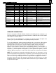
E250P/P12SW subwoofers JBL E250P/P12SW Powered Sub/ Plate Amp LINE VOLTAGE US 120vac/60Hz EU 230vac/50-60Hz Yes/No Yes Yes Hi/Lo Line 108-132 207-264 Nom. 120 230 Unit QA Test Limits n/a Ohms Watts Watts n/a n/a 140 130 Parameter Specification Amp Section Type (Class AB, D, other) D Load Impedance (speaker) 5.
E250P/P12SW subwoofers Parameter Turn-on Transient Turn-off Transient Efficiency Efficiency Stand-by Input Power Power Cons. @ rated power Specification 50 50 Unit mV-peak mV-peak QA Test Limits Conditions 2v-pp @ Speaker Outputs 2v-pp @ Speaker Outputs 65 % 64 24 234 Watts Watts 26 240 @ nom. line voltage @ nom.
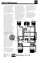
E250P/P12SW subwoofers Analog Receiver/Processor – Speaker-Level Connections Use this installation method only with an analog receiver/ processor that does not have digital processing or bass management, and also does not have a subwoofer output or a volume-controlled preamp (line-) level output: Connect the speaker wires for both your main left and right speakers, and for the subwoofer, to the same speaker terminals on your receiver or amplifier.
E250P/P12SW subwoofers Analog Receiver/Processor – Line-Level Connections Use this installation method with an analog receiver/ processor that does not have digital processing or bass management, and that is equipped with a full-range subwoofer output or a volumecontrolled preamp (line-) level output: Use RCA-type interconnect cables to connect the linelevel subwoofer outputs on your receiver or amplifier to the line-level inputs on the subwoofer.
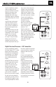
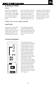
E250P/P12SW subwoofers OPERATION Power When the unit is plugged in and the power switch is on and no signal is received, the LED on the top of the unit*will turn red. When a signal is present, the LED will turn green. Note: It will take several minutes for the LED to turn from green to red after the input signal to the subwoofer is removed.
E250P/P12SW subwoofers Phase Control The Phase Control determines whether the subwoofer’s piston-like action moves in and out in phase with the main speakers or opposite the main speakers. There is no correct or incorrect setting. Proper phase adjustment depends on several variables such as subwoofer placement and listener position. Adjust the phase switch to maximize bass output at the listening position. Remember, every system, room and listener is different.
E250P 15 6 7 10 Exploded View 17 Amplifier – Not for Sale 14 11 16 12 8 9 13 Ref# Part Number Description Qty 6 7 8 9 10 11 12 13 14 15 351348-001 338125-002 336486-001 763-31110-40 908302-012 903802-016 338128-002 336799-001 351307-001 333249-003 16 17 333249-001 351243-001 903401-012 PLATE,LED/LOGO-E250P ASY,LED-E250P/E250P ASY,FOOT,PLSTC- E250P SCREW, 8 X 2 1/2,TR,PH,PB,BLK ZINC,LCS (FOOT) SCREW, PB,HXS,#6x.
P 12S W 2 Amplifier – Not for Sale 3 Exploded View 1 10 4 5 6 8 9 7 Ref# Part Number Description Qty 1 2 3 4 5 6 7 8 9 10 352024-003 333249-001 882-41110-12 903802-016 351243-001 338128-002 336799-001 336486-001 883-31110-40 361872-001 ASY, GRILLE, BLK, FRNT CUP,GRILLE SCREW, 6 X 3/4,PAN,PH,PB,BLK ZINC,LCS (AMPLIFIER) SCREW, PB,HXS,#8x1",ZINC (WOOFER) RING,TRIM,12" ASY, WOOFER,12" DCR 4.
E250P/P12SW subwoofers TEST SET-UP AND PROCEDURE General Function UUT = Unit Under Test 1) Connect a pair of level input cables (RCA) from signal generator to either Right or Left Level input on UUT. LEVEL control should be full counterclockwise (MIN). Make sure the LFE/Normal switch is in the NORMAL position. 2) Turn on generator, adjust to 100mV, 50Hz. 3) Plug in UUT; Turn Main Power switch ON. LED may be either Red or Green. Turn LEVEL control full clockwise (MAX).
E250P/P12SW subwoofers & P10SW & P12SW 14
E250P subwoofer Service Bulletin Service bulletin # JBL2005-01 December 2005 Warranty labor rate: MINOR repair To: All JBL Service Centers Model: E150P, E250P Subwoofers Subject: “Chirp” Noise on Power-Up In the event you receive an E150P or E250P with the complaint: “the subwoofer make a slight “chirp” noise when it becomes active from the stand-by mode”, perform the following modification. Synopsis: Change C65 PE capacitor from 470µf to 47µf. 1) Remove the amplifer from the enclosure.
E250P/P12SW subwoofers TECH TIPS Troubleshooting tips and solutions to common service problems For models: E150P,E250P P10SW, P12SW PB10,PB12 (Revision 2) * TIP# JBLTT2003-04 Rev2 Subject: Replacing MOSFETS Q18, Q22 In the event you need to replace MOSFET transistors Q18 or Q22 as part of a repair, it is important to use ONLY: • JBL part# 051-640001-000 • Or JBL part# FE106401110 • Or only the brands: International Rectifier, or Fairchild.
E250P/P12SW subwoofers DETAILED TROUBLESHOOTING A. Power Amp Section Resistance from S+ (SPK O/P) to GND should be >1M Ω (NO LOAD) Resistance Check Resistance from V+ (C6 P+) to V- (C8 P-) gradually Fully CHARGED should read >10k Ω Resistance from V+ (C6 P+) to S+ (SPK O/P) should read >1MΩ Resistance from V- (C8 P-) to S+ (SPK O/P) should read >1M Ω 2. Power Up LED RED With a 5mV signal to Low level input, LED should change to GREEN -Voltage measurements (DVM) OP AMP P-U4(1) P-U4(7) 0Vrms 11.84VDC 7.
E250P/P12SW subwoofers DETAILED TROUBLESHOOTING (CONT'D) - Voltage measurements U2(1) U2(14) U2(8) U3(7) OP AMP U3(1) 306.9mV 461mV 460mV 658mV 628mV U3(14) U3(8) U5(7) U5(1) SPEAKER O/P 598mV 2.326V 2.02V 3.57V 23.33V 2. High Level Input Sensitivity -Set up Turn level, X’OVER FREQ POT Fully CW and LFE switch off Set Generator at 1.3V@50Hz Signal to High level input -Voltage measurements 15.3V at speaker output 3.
E250P/P12SW subwoofers DETAILED TROUBLESHOOTING (CONT'D) FLOW CHART CAUTION : SPEAKER OUTPUT IS FLOATING AND IS NOT PROTECTED AGAINST A SHORT TO GROUND. ALL TEST INSTRUMENTS CONNECTED TO THE OUTPUT MUST BE FLOATING. ATTACH THE SCOPE PROBE TIP TO S - and REFERENCE LEAD TO S+.
E250P/P12SW subwoofers 20
E250P/P12SW subwoofers 21
E250P/P12SW subwoofers 22
E250P/P12SW subwoofers 23
E250P/P12SW subwoofers E250P/P12SW (120v) Electrical Parts List Part Number Description Reference Designator Qty Resistors 020-220497-120 Carbon Film 1 MOF Resistor 2K2 1/4W J 1K 1W J R11 021-100401-120 R103 1 021-120403-020 MOF Resistor 1K2 3WS J 8x20 R9 1 021-120405-020 MOF Resistor 1K2 5WS J 8x25 R6 1 021-220202-120 MOF Resistor 22R 2W(S) J MB TYPE 15x8 R10 1 022-500003-020 KNP Resistor 0R05 3WS J FK TYPE R104 1 024-000098-120 SMD Resistor 0R 1/8W J 0805 R125,126 2
E250P/P12SW subwoofers Part Number Description Reference Designator Qty R70 1 024-470698-120 SMD Resistor 470K 1/8W J 0805 024-470798-120 SMD Resistor 4M7 1/8W J 0805 R60 1 024-487498-100 SMD Resistor 4K87 1/8W F 0805 R51,53 2 024-510398-120 SMD Resistor 510R 1/8W J 0805 R57 1 024-560598-120 SMD Resistor 56K 1/8W J 0805 R122 1 024-620398-100 SMD Resistor 620R 1/8W F 0805 R16,18 2 024-680498-120 SMD Resistor 6K8 1/8W J 0805 R46,91,40,41,43,42 6 024-680598-120 SMD Resis
E250P/P12SW subwoofers Part Number Description Reference Designator Qty 051-005600-100 PNP Transistor PN:MPSW56RLRA TO-92 (ON) Q3 1 051-222200-100 NPN Transistor PN:MPS2222ARLRA TO-92 Q21 1 051-290700-100 PNP Transistor PN:MPS2907A RLRA TO-92 Q19,23 2 051-540101-000 PNP Transistor PN:2N5401 TO-92 Q1 1 051-555100-000 NPN Transistor PN:2N5551 TO-92 Q17 1 051-640001-000 MOSFET N-Channel PN:IRF640N TO-220 (IR) Q18,22 2 052-400080-000 Bridge Regulator PN:RS804 400V,8A BR1 1
E250P/P12SW subwoofers Part Number Description Reference Designator Qty 063-010012-000 Brckt for pwr transistor P/N:TRK-1 063-321100-001 E250P Faceplate 322x105.7x15mm BLK (94V0)ABS E250P 063-321101-000ZR P12SW Faceplate 322x105.7x15mm BLK (94V0)ABS P12SW 063-531808-000 Bucket 322x105.7x146.5mm blk (94VO) 071-100608-100 Fiber Washer OD=8mm ID=3.2 t=1 (red) 071-100851-000 Washer ID=5.1 OD=12 t=1m/m 072-010007-000 RCA Jack SCJ-1020 2P(G) wht, red 072-040039-000 Terminal PC205 (t=0.
E250P/P12SW subwoofers Semiconductor Pinout Diagrams 2N5401 Q1 MOSFET IRF640 Q18, 22 OPAMP, QUAD TL074CDR U2, 3 3 Collector 1. G 2. D 3.
E250P/P12SW subwoofers SCHEMATICS NOTE: THIS VOLTAGE IS REFERENCED TO -V, NOT CIRCUIT GROUND P12SW Value of C65 = 47uf See service bulletin for E250P NOTE: THIS VOLTAGE IS REFERENCED TO -V, NOT CIRCUIT GROUND 29
NOTE: THIS VOLTAGE IS REFERENCED TO -V, NOT CIRCUIT GROUND E250P/P12SW subwoofers 30