
User Manual


3
L100 Classic Owner’s Manual
English
CONNECTIONS
CAUTION: Make sure that all of the system’s electrical components are turned OFF (and preferably
unplugged from their ac outlets) before making any connections.
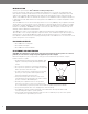
Speakers and amplifiers have corresponding positive and negative (“+” and “–”)
connection terminals. The L100 Classic has color-coded connection terminals. The
“+” terminal is red, while the “–” terminal is black. See the illustration on the right.
The L100 Classic is designed so that a positive voltage at the “+” (red) terminal
will cause the speaker drivers to move outward (toward the room).
We recommend using a high-quality speaker cable with polarity coding. The side
of the wire with a ridge or other coding is usually considered positive polarity (“+”).
To ensure proper polarity, connect each “+” terminal on the back of the amplifier
or receiver to the respective “+” (red) terminal on each speaker. Connect the “–”
(black) terminals in a similar way. See your receiver or amplifier’s owner’s manual
to confirm its connection procedures.
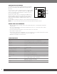
BASIC SINGLE-WIRE CONNECTION
Connect the amplifier to each speaker as shown in
the illustration on the right.
IMPORTANT: Do not reverse polarities (i.e., “+”
to “–” or “–” to “+”) when making connections.
Doing so will cause poor stereo imaging and
diminished bass performance.
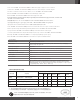
The L100 Classic’s gold-plated speaker terminals
can accept a variety of wire connector types:
bare wire, spade connectors, pin connectors
and banana connectors.
USING BARE WIRE OR PIN CONNECTORS:
IMPORTANT: Make sure that the (+) and (–) wires or
pins do not touch each other or the other terminal.
Touching cables can cause a short circuit that can
damage your receiver or amplifier.
USING SPADE CONNECTORS:
IMPORTANT: Make sure the (+) and (–) spade connector
blades do not touch each other or the other terminal.
Touching blades can cause a short circuit that
can damage your receiver or amplifier.
USING BANANA CONNECTORS:
Negative (-)
Terminal
Positive (+)
Terminal
+
-
Receiver or Amplifier
(one channel shown)
Speaker
Connector Panel
A. Unscrew Cap
B. Insert Bare Wire or
Pin Connector through
Hole in Post
C. Tighten Cap
to Secure
A. Unscrew Cap
B. Insert Space
Connector Blades
around Post
C. Tighten Cap
B. Insert Banana Connector
into Hole in Cap
A. Tighten Cap